System and method to align a source resonator and a capture resonator for wireless electrical power transfer

a wireless electrical power and source resonator technology, applied in the direction of electric vehicles, circuit monitoring/indication, transportation and packaging, etc., can solve the problems of poor repeatability, time-consuming methods, and difficulty for the vehicle operator to judge where to park the vehicl

Active Publication Date: 2014-05-15
APTIV TECH LTD
View PDF7 Cites 69 Cited by
  • Summary
  • Abstract
  • Description
  • Claims
  • Application Information

AI Technical Summary

Benefits of technology

[0010]The controller may additionally be configured to determine a charging time for the battery based on the current state of charge and the power transfer efficiency and the display device is configured to indicate the charging time based on commands from the controller.
[0011]The controller may further be configured to determine whether the efficiency score exceeds a threshold and the display device is configured to indicate a request to reinitiate a parking process when the efficiency score is below the threshold based on commands from the controller.
[0012]In another embodiment of the present invention, a method to align a source resonator and a capture resonator is provided. The source resonator is coupled to an electrical power source to provide an electric current to the source resonator that causes the source resonator to emit a magnetic charging signal. The capture resonator is configured to wirelessly receive the magnetic charging signal and provide electrical power based on the magnetic charging signal. The capture resonator is disposed on a vehicle when the vehicle is being guided to a parked position. The method includes the steps of providing a display device and determining a relative distance and a relative direction between the source resonator and the capture resonator. The method further includes the steps of indicating the relative distance and the relative direction between the source resonator and the capture resonator via the display device, determining a power transfer efficiency of electrical power between the source resonator an

Problems solved by technology

However, some operators object to having to ‘plug-in’ their vehicle each time the vehicle is parked.
However, as the source resonator and the capture resonator may be underneath the vehicle and/or out of the vehicle operator's view, it is difficult for the vehicle operator to judge where to park the vehicle so that the source resonator and the

Method used


Image

  • System and method to align a source resonator and a capture resonator for wireless electrical power transfer
  • System and method to align a source resonator and a capture resonator for wireless electrical power transfer
  • System and method to align a source resonator and a capture resonator for wireless electrical power transfer

Examples


Embodiment Construction

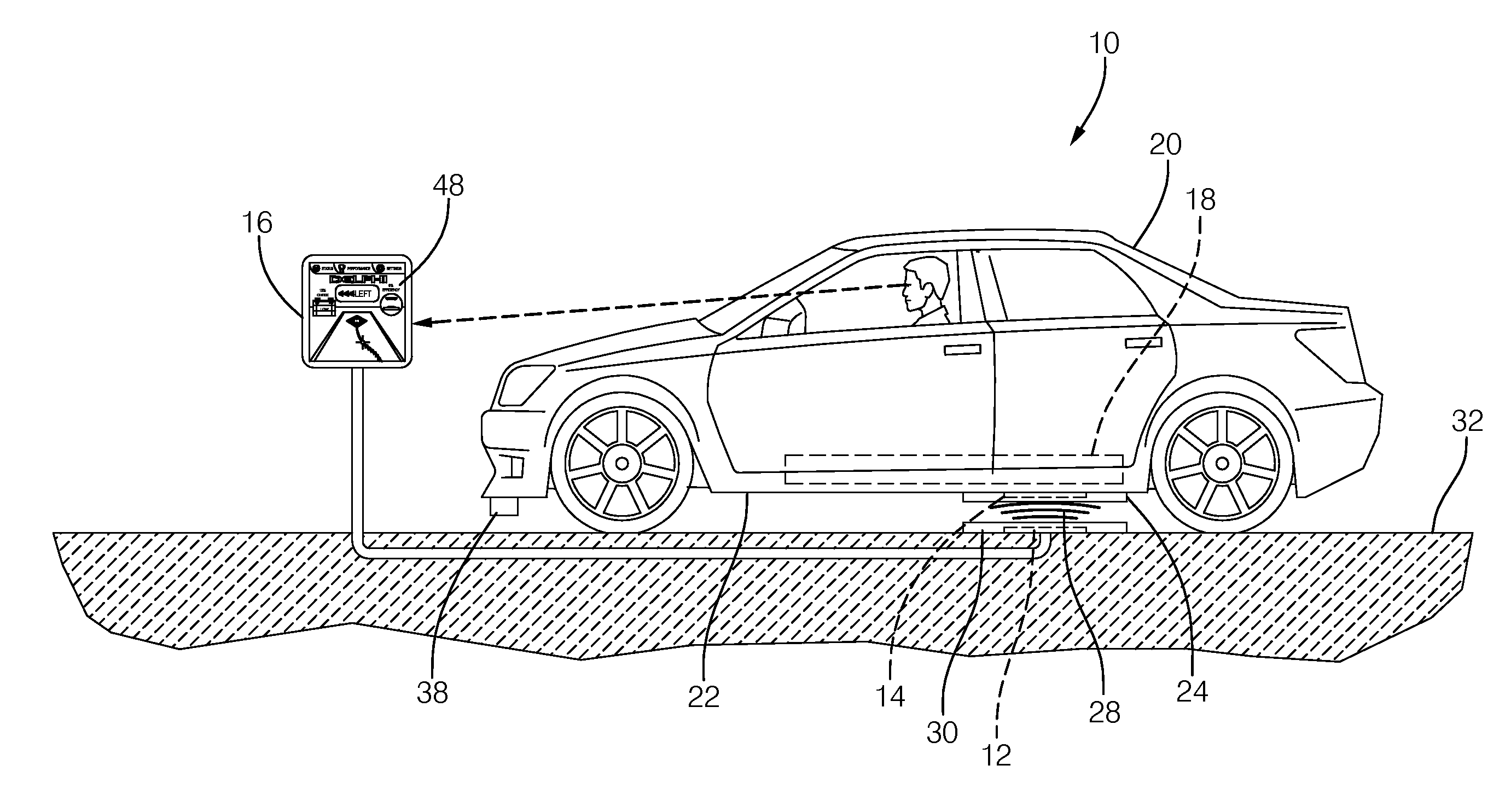
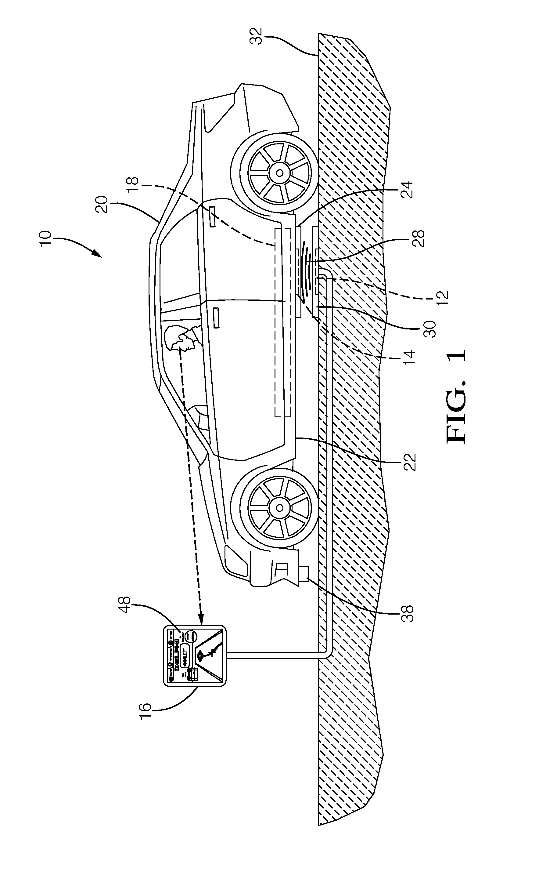
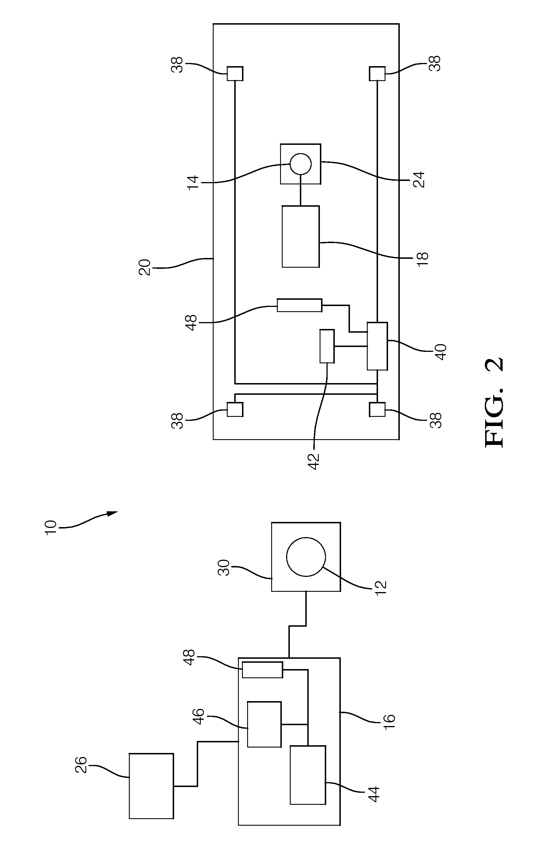
[0024]Described herein are a system and a method for aligning a source resonator and a capture resonator, such as those used in an electric vehicle charging system, in order to maximize the efficiency of electrical power transfer between the source resonator and the capture resonator. The source resonator emits a magnetic charging signal that may be amplitude modulated at a resonant frequency of the source resonator and the capture resonator. The charging signal is transmitted to the capture resonator wherein the charging signal induces an electric current. The capture resonator may be attached to a vehicle and the vehicle may be maneuvered to align the source resonator and the capture resonator so that the source resonator and capture resonator are aligned for maximum power transfer efficiency when the vehicle is parked. Because the capture resonator is typically located out of the direct view of a vehicle operator, the system includes a sensor and a controller to determine a relat...


PUM


Abstract

A system and a method to provide alignment between a source resonator and a capture resonator. The system and method may be used to align a vehicle having a capture resonator to the source resonator of a wireless inductive battery charging system for an electric vehicle. The system includes a display device, a sensor to determine a location of the source resonator relative to the capture resonator, and a controller in communication with the source resonator, the capture resonator, the sensor, and the display device. The controller is programmed to determine a relative distance and a relative direction between the source resonator and the capture resonator, determine a transfer efficiency of electrical power between the source resonator and the capture resonator. The display device is configured to indicate the relative distance and the relative direction between the source resonator and the capture resonator and indicate the transfer efficiency.

Description

TECHNICAL FIELD OF INVENTION[0001]The invention generally relates to wireless electrical power transfer between a source resonator and a capture resonator, and more particularly relates to a system and method to align the source resonator to the capture resonator using a graphical display device to maximize power transfer efficiency.BACKGROUND OF INVENTION[0002]Electric vehicles and electric-hybrid vehicles are gaining in popularity with consumers. The electric motors in these vehicles are typically powered from multiple storage batteries disposed in a battery pack in the vehicle. If the battery needs to be recharged while the vehicle is parked, a wired coupling device is connected to the vehicle, typically by the vehicle operator. However, some operators object to having to ‘plug-in’ their vehicle each time the vehicle is parked.[0003]Wireless or connector less battery chargers have been proposed, see U.S. Pat. No. 5,498,948 issued Mar. 12, 1996 to Bruni et al. and U.S. Pat. No. 8,...

Claims


Application Information

Patent Timeline
IPC IPC(8): H02J7/00
CPCH02J7/0047H02J7/0042H02J7/00B62D15/029H02J2310/48H02J7/0048H02J50/90H02J50/12
Inventor FISHER, SCOTT F.
Owner APTIV TECH LTD
Why Eureka
Try Eureka