Brake booster fault diagnostics

a technology of brake booster and fault diagnosis, which is applied in the direction of rotary clutches, braking systems, fluid couplings, etc., can solve problems such as insufficient knowledge of known methods

Inactive Publication Date: 2014-05-22
FORD GLOBAL TECH LLC
View PDF12 Cites 22 Cited by
  • Summary
  • Abstract
  • Description
  • Claims
  • Application Information

AI Technical Summary

Benefits of technology

[0004]As such, one example approach for diagnosing faults in brake booster operation in systems supplying brake booster vacuum via the intake manifold and one or more vacuum-powered pumps includes, when braking is suspended, indicating degradation based on expected BB vacuum, the expected BB vacuum based on expected mass air flow from the BB to the intake manifold when measured BB vacuum is less than intake manifold vacuum, and based on expected mass air flow from the BB to one or more vacuum-powered pumps when measured BB vacuum is not less than intake manifold vacuum. In this way, it may be possible to determine whether the brake booster is functioning properly even in systems where several active vacuum sources (e.g., ejectors/asprirators/venturis and driven pumps) are coupled with the brake booster in addition to the intake manifold. Specifically, by dividing brake booster behavior into two sim

Problems solved by technology

However, the diagnostic methods employed in such systems may require brake actuation or detection of whether a braking cycle has occurred.
Further, such systems may include physical models with integrators, and therefore may produce results that are highly dependent on the initial conditions (e.g., the initial measurement of pressure in the

Method used


Image

  • Brake booster fault diagnostics
  • Brake booster fault diagnostics
  • Brake booster fault diagnostics

Examples


Embodiment Construction

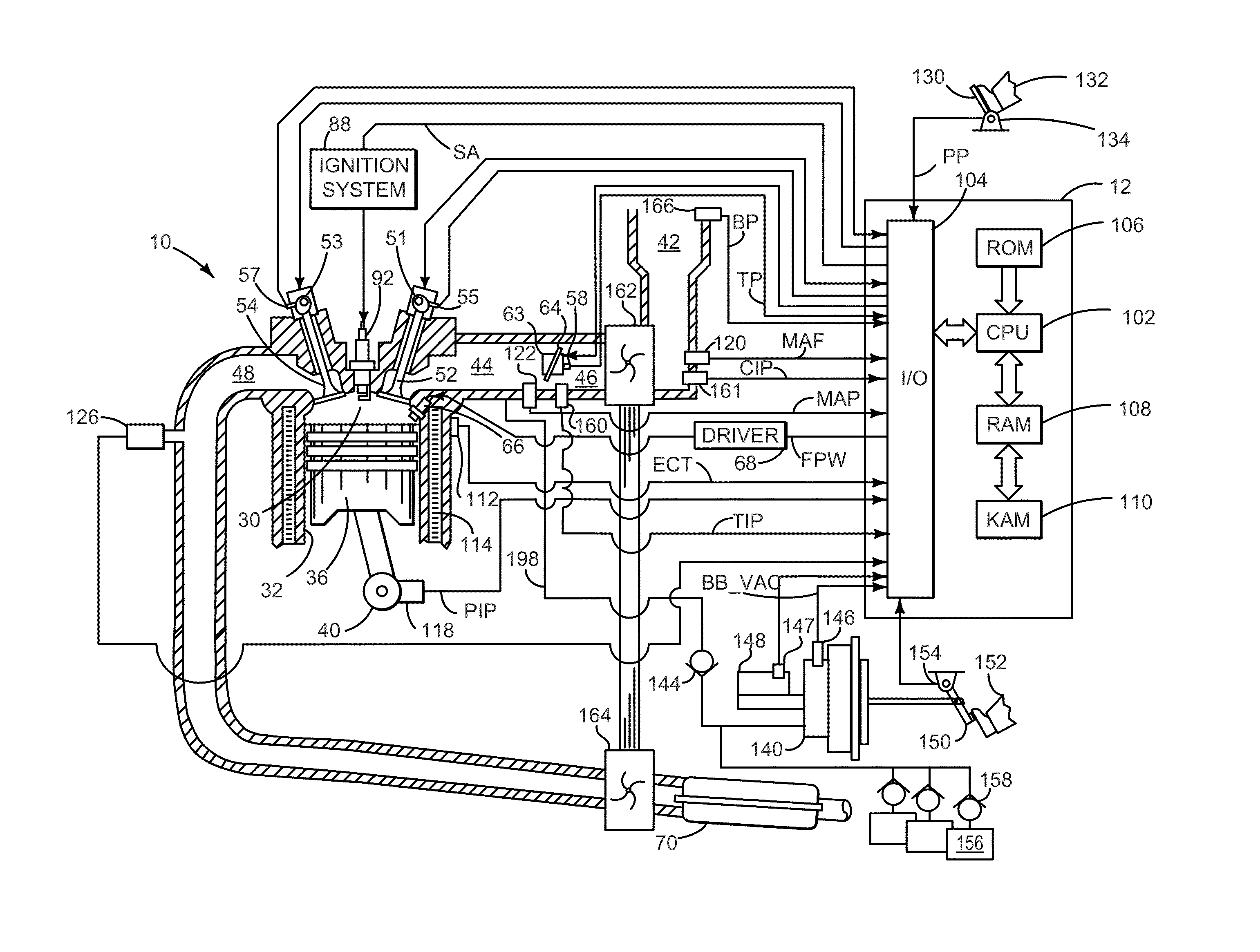
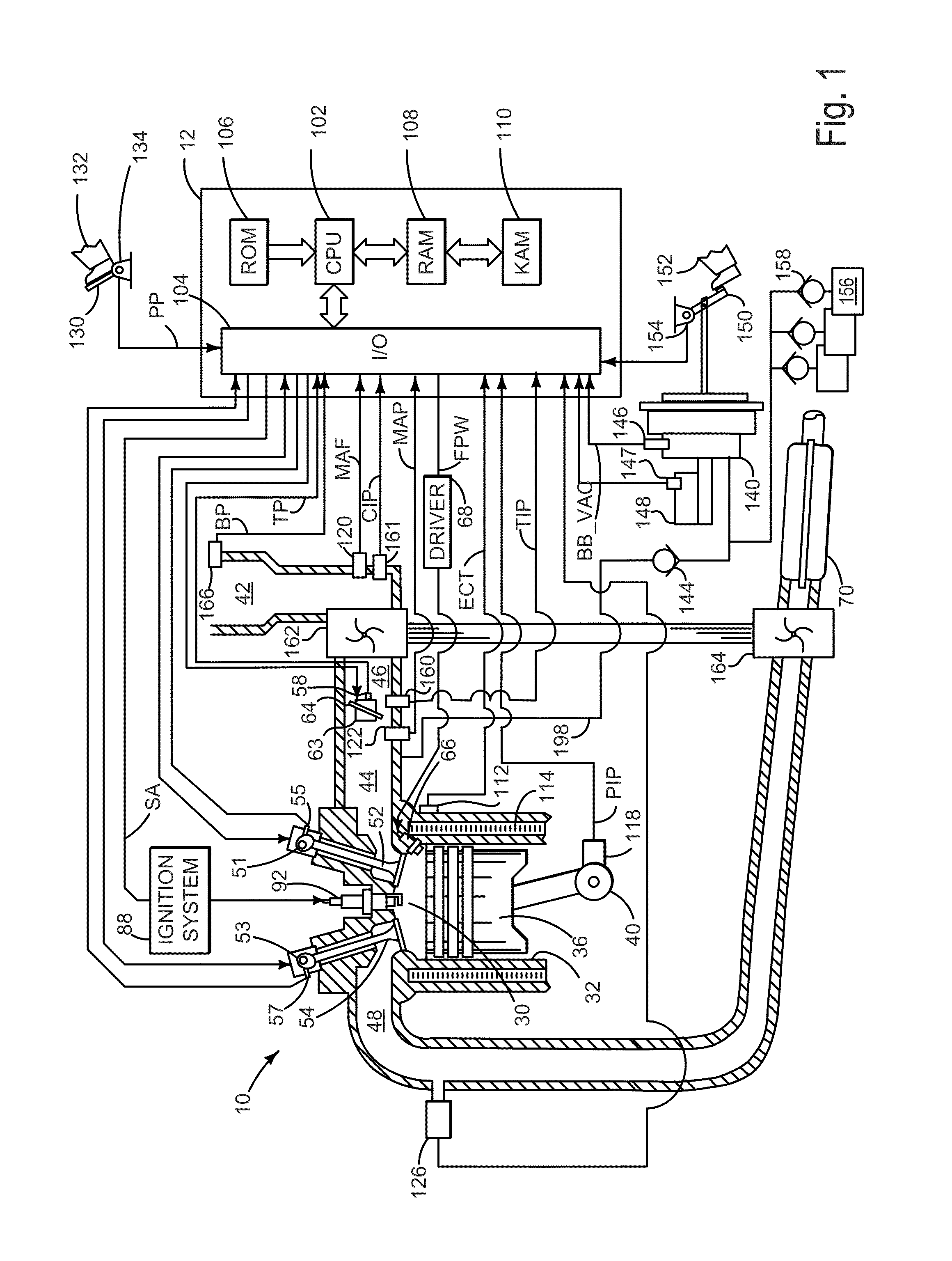
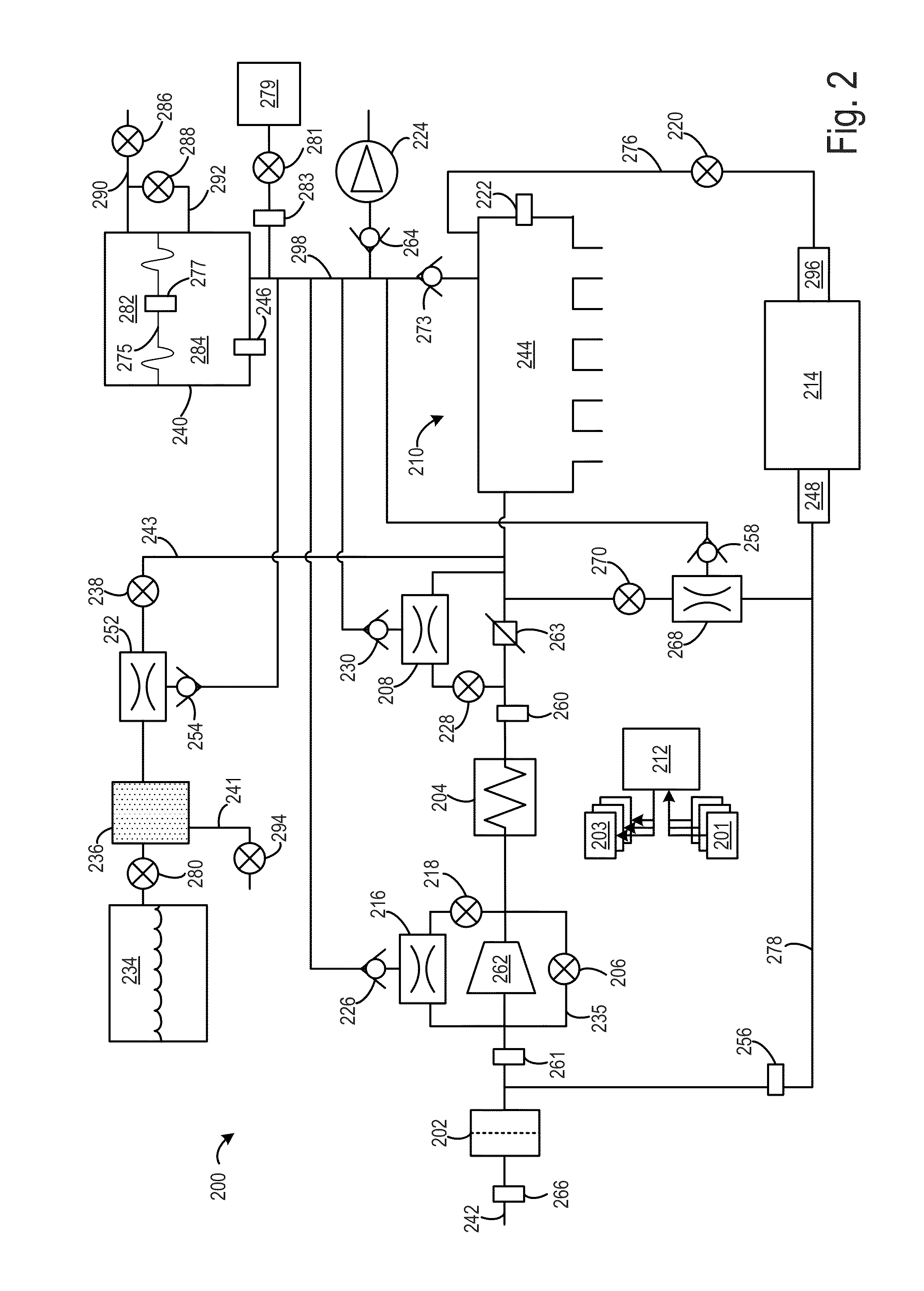
[0012]Methods and systems for brake booster fault diagnosis when braking is suspended are provided herein. As shown in FIGS. 1 and 2, an engine system may include a brake booster to amplify vehicle operator braking force, and vacuum may be supplied to the brake booster by the intake manifold as well as one or more vacuum-powered pumps. As shown in FIG. 2, these vacuum-powered pumps may include various ejectors / aspirators / venturis as well as engine-driven or electrically-driven pumps. As shown in FIG. 3, a method for brake booster fault diagnosis may include comparing expected brake booster vacuum with measured brake booster vacuum, and indicating a fault when the difference between the two values exceeds a threshold. In one example, as shown in FIG. 4, the expected brake booster vacuum is computed differently depending on whether intake manifold vacuum or vacuum from one or more vacuum-powered pumps dominates evacuation of the brake booster. As shown in FIG. 4, expected brake booste...


PUM


Abstract

Methods and systems for indicating brake booster degradation when braking is suspended may include comparing expected brake booster vacuum with measured brake booster vacuum, and indicating a fault when the difference between the two values exceeds a threshold. In one example, the expected brake booster vacuum is computed differently depending on whether intake manifold vacuum or vacuum from one or more vacuum-powered pumps dominates evacuation of the brake booster. Expected brake booster vacuum may be computed based on expected brake booster mass air flow and brake booster volume; when measured brake booster vacuum is less than intake manifold vacuum, expected brake booster mass air flow may be computed as a function of intake manifold vacuum and measured brake booster vacuum, whereas expected brake booster mass air flow may be computed based on flow characteristics of the pump(s) when measured brake booster vacuum is not less than intake manifold vacuum.

Description

BACKGROUND AND SUMMARY[0001]Vehicles may use a brake booster in an internal combustion engine which uses vacuum to amplify driver braking force. As brake booster operation depends upon the pressure in a vacuum chamber of the brake booster, it may be important to diagnose whether the vacuum chamber evacuation and replenishment functionality is working properly.[0002]In some systems, brake booster vacuum may be supplied by the intake manifold alone. Such systems may diagnose brake booster operation based on the relationship between sensed pressures in the intake manifold and the brake booster vacuum chamber, in some examples. However, the diagnostic methods employed in such systems may require brake actuation or detection of whether a braking cycle has occurred. Further, such systems may include physical models with integrators, and therefore may produce results that are highly dependent on the initial conditions (e.g., the initial measurement of pressure in the brake booster vacuum c...

Claims


Application Information

Patent Timeline
IPC IPC(8): B60T13/66
CPCB60T13/66B60T13/72B60T17/22
Inventor PURSIFULL, ROSS DYKSTRACUNNINGHAM, RALPH WAYNE
Owner FORD GLOBAL TECH LLC
Why Eureka
Try Eureka