
Piston-operated pipette with interchangeable displacement unit

a technology of displacement unit and piston, which is applied in the field of piston-operated pipette, can solve the problems of injuries or damage, manual overturning of magnetic force only with difficulty, and inability to solve the problem of manual overturning of magnetic force between the two components, and achieve the effect of efficient handling and ergonomic operation

Active Publication Date: 2014-05-22
BRAND GMBH CO KG
View PDF11 Cites 2 Cited by
  • Summary
  • Abstract
  • Description
  • Claims
  • Application Information

AI Technical Summary

Benefits of technology

This patent describes a piston-operated pipette with a detachable mechanical connection that can be easily and safely handled. The invention is based on the idea of weakening the magnetic force between the drive unit and the displacement unit using an additional mechanical means, making it easier for the operator to remove the displacement unit from the drive unit and reattach it in a different direction. The magnetic connection is made to be more practical and safe than previous versions, preventing injury from sudden breaking of the connection. The mechanical means for breaking the magnetic connection can be easily and safely actuated by hand, making the structure simple and economical. The construction is mechanically durable and advantageous in releasing the magnetic connection by force, but a retaining device is also used to prevent complete breaking of the connection.

Problems solved by technology

In practice, it has been shown that the magnetic force can be overcome manually only with difficulty.
Separation takes place suddenly, is unpleasant, and under certain circumstances can lead to injuries or damage.
When the displacement unit is joined to the drive unit by the magnetic force, between the two components injuries can likewise occur.
Fundamentally, one or more electromagnets are required which increases the weight of the piston-operated pipette considerably.

Method used


Image

  • Piston-operated pipette with interchangeable displacement unit
  • Piston-operated pipette with interchangeable displacement unit
  • Piston-operated pipette with interchangeable displacement unit

Examples


Embodiment Construction

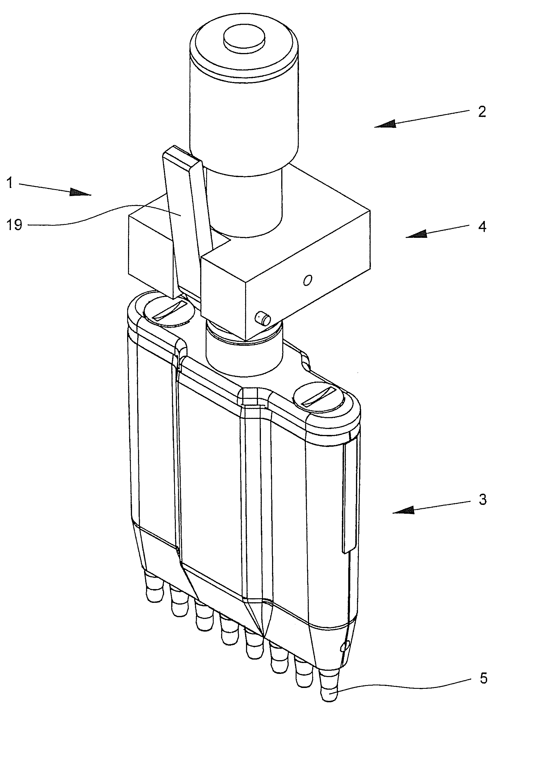
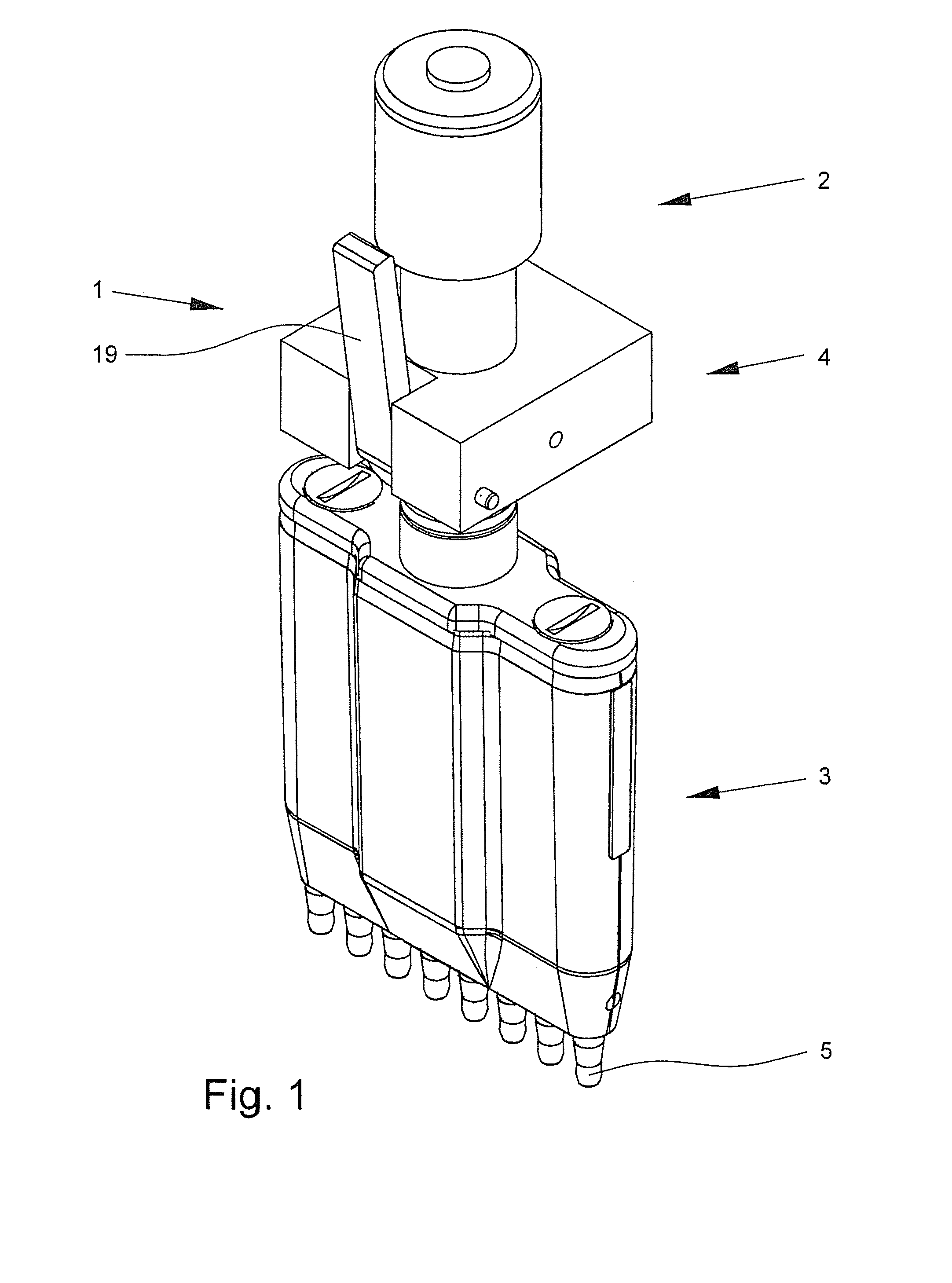
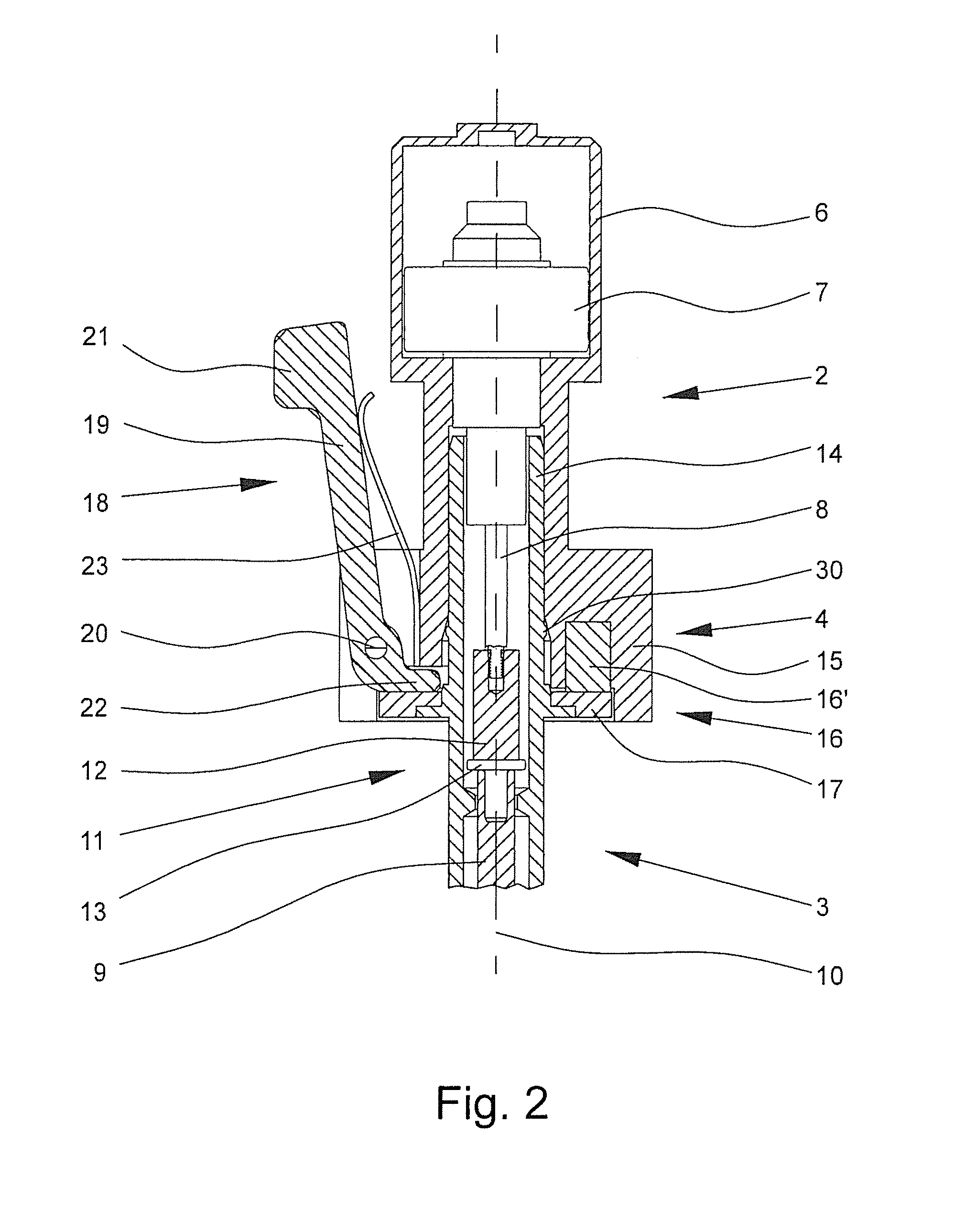
[0036]FIG. 1 shows a piston-operated pipette 1 for transferring liquid with a drive unit 2, a displacement unit 3 and a coupling apparatus 4 which connects the two units. On the bottom end of the displacement unit 3, there are several shafts 5 for joining of pipette tips (not shown). The aspiration and ejection of the liquid take place via a piston 9′ and a cylinder 9″ which are located in the displacement unit 3 and which change the air volume in the pipette tips and beyond. FIG. 3 shows this, for example, in the section of the displacement unit 3, which section is open to the left.

[0037]FIG. 1 shows a multichannel piston-operated pipette 1 with several shafts 5, but the teaching can also be applied to a piston-operated pipette 1 with a single channel displacement unit 3. Likewise, the teaching can be used in positive displacement pipettes. Therefore, any form of the piston-operated pipette according to DIN EN ISO 8655-2 is suitable for use in accordance with the invention.

[0038]FI...


PUM


Abstract

A piston-operated pipette with a drive unit with a piston drive and a displacement unit mounted on the drive unit, the displacement unit being dismountable from the drive unit, the drive unit having an actuating drive for the piston drive and a receiving section for the displacement unit. The displacement unit has a fastening section which fits the receiving section of the drive unit, there being a first detachable mechanical connection between the actuating drive and the piston drive and there being a second detachable mechanical connection between the receiving section of the drive unit and the fastening section of the displacement unit. The second detachable mechanical connection is made as a magnetic connection. A mechanical arrangement for breaking the magnetic connection is provided between the receiving section and the fastening section, the magnetic connection being releasable by actuating the arrangement for breaking the magnetic connection.

Description

BACKGROUND OF THE INVENTION[0001]1. Field of the Invention[0002]The invention relates to a piston-operated pipette with a drive unit and a displacement unit which is mounted on the drive unit, displacement unit having a piston drive for at least one piston and being dismountable from the drive unit. In practice, these piston-operated pipettes are used for transfer of liquids using pipette tips.[0003]2. Description of Related Art[0004]The German Patent Application DE-A-198 26 065 discloses a piston-operated pipette which shows a displacement unit as an air-displacement or positive displacement version. The connection on the piston-operated pipette between the drive unit and the displacement unit takes place via coupling apparatus composed of a magnet and a ferromagnetic element as well as means which fit axially into one another. On the one hand, there is a detachable mechanical connection between the piston actuation and the piston rod in the center of the piston-operated pipette. O...

Claims


Application Information

Patent Timeline
Patent Type & Authority Applications(United States)
IPC IPC(8): B01L3/02
CPCB01L3/0217B01L3/0275B01L2200/028
Inventor GEHRIG, STEFFENHOCHHOLZER, GUNTERSCHAUB, BURKARD
Owner BRAND GMBH CO KG
Learn More