
Quiet electromechanical switch device

Active Publication Date: 2014-05-22
PASS SEYMOUR
View PDF8 Cites 11 Cited by
  • Summary
  • Abstract
  • Description
  • Claims
  • Application Information

AI Technical Summary

Benefits of technology

This invention is for a better electromechanical switch that is quieter, easy to operate, and has a small angle of rotation between switch positions. This switch can also be used in different form factors, like a modular framing system, and doesn't require fasteners to be securely installed within the device box.

Problems solved by technology

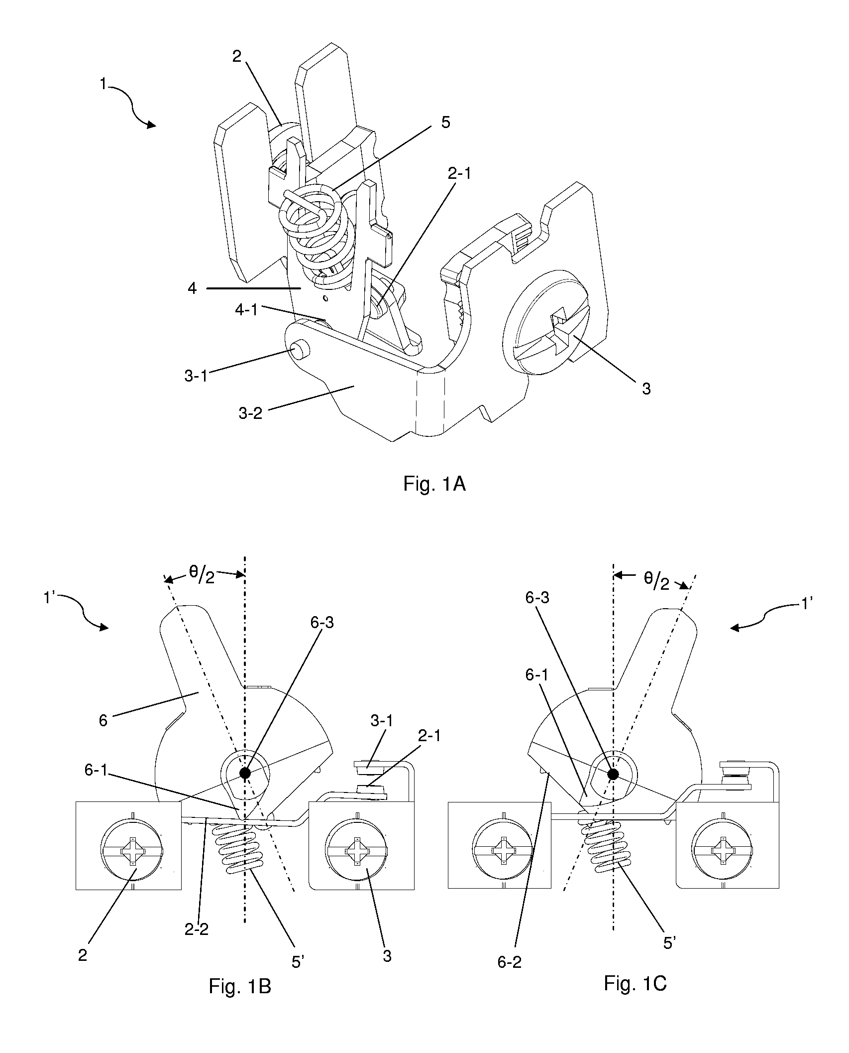
When the pendulum contact 4-1 strikes the opposing traveler contact 2-1, the closing of the contacts (2-1, 4-1) creates a loud noise that some consumers find annoying.
Hence, one drawback to the switch mechanism depicted in FIG. 1A relates to the loud actuation noise it produces when the pendulum contact strike the traveler contact.
Thus, the drawbacks associated with this switch type relate to the large angle of rotation between switch positions and the loud noise that is sometimes associated with actuating the switch.
However, there are drawbacks associated with electronic switches.
Electronic switches are relatively expensive and not as robust as electro-mechanical switches.
Accordingly, electronic switches are not as reliable and must be replaced more frequently than electro-mechanical switches.
Turning now to another consideration, there are several drawbacks associated with conventional installation methods and conventional protective electrical wiring devices.
Conventional protective electrical wiring devices often do not make efficient use of space.
In addition, mounting the wiring device's ground strap to the device box is tedious, time consuming, and therefore costly.
Moreover, in multi-gang installations, the finished look is often ragged because the plurality of electrical devices and their respective cover plates are typically not in alignment.
Retrofitting an electrical installation can also be problematic from the standpoint of the finished look because the device box, or an old work box, may not be precisely aligned to the plane of the wall surface.
This is especially true if the wall surface itself is uneven.
Thus, a homeowner may inadvisably remove the faceplate cover from an energized wiring device and inadvertently become exposed to a shock hazard from the “hot” electrical wiring.

Method used


Image

  • Quiet electromechanical switch device
  • Quiet electromechanical switch device
  • Quiet electromechanical switch device

Examples


Embodiment Construction

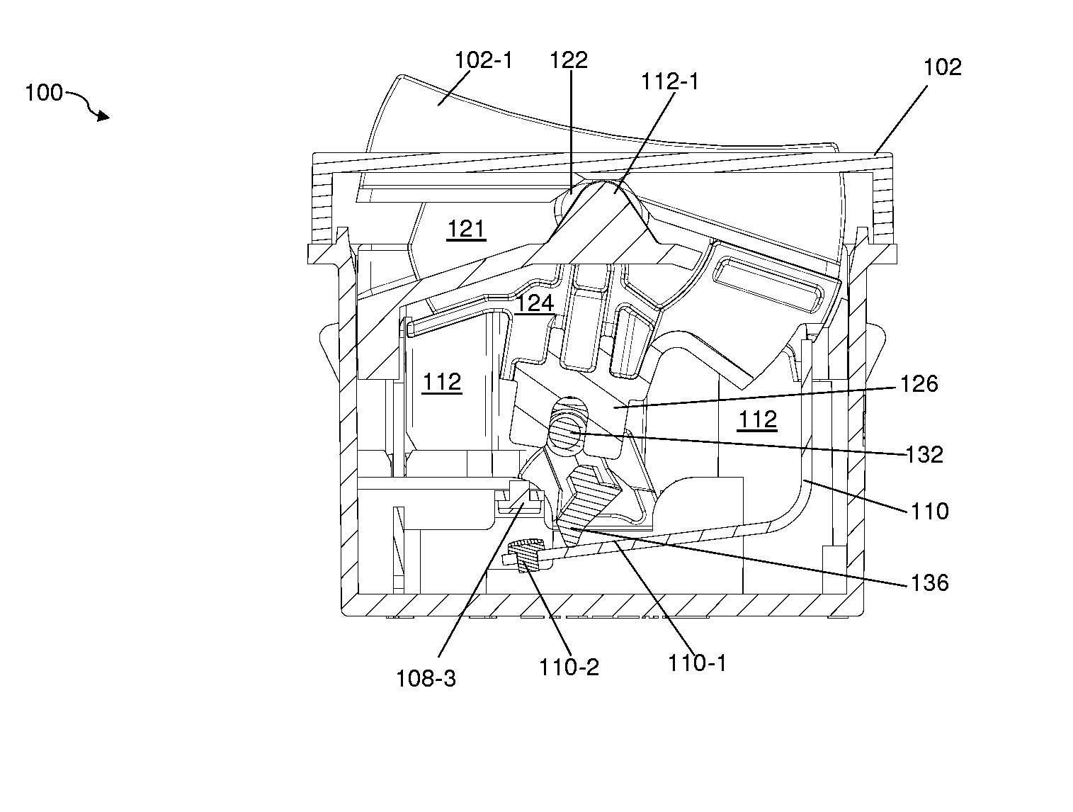
[0037]Reference will now be made in detail to the present exemplary embodiments of the invention, examples of which are illustrated in the accompanying drawings. Wherever possible, the same reference numbers will be used throughout the drawings to refer to the same or like parts. An exemplary embodiment of the switch of the present invention is shown in FIG. 4, and is designated generally throughout by reference numeral 100.

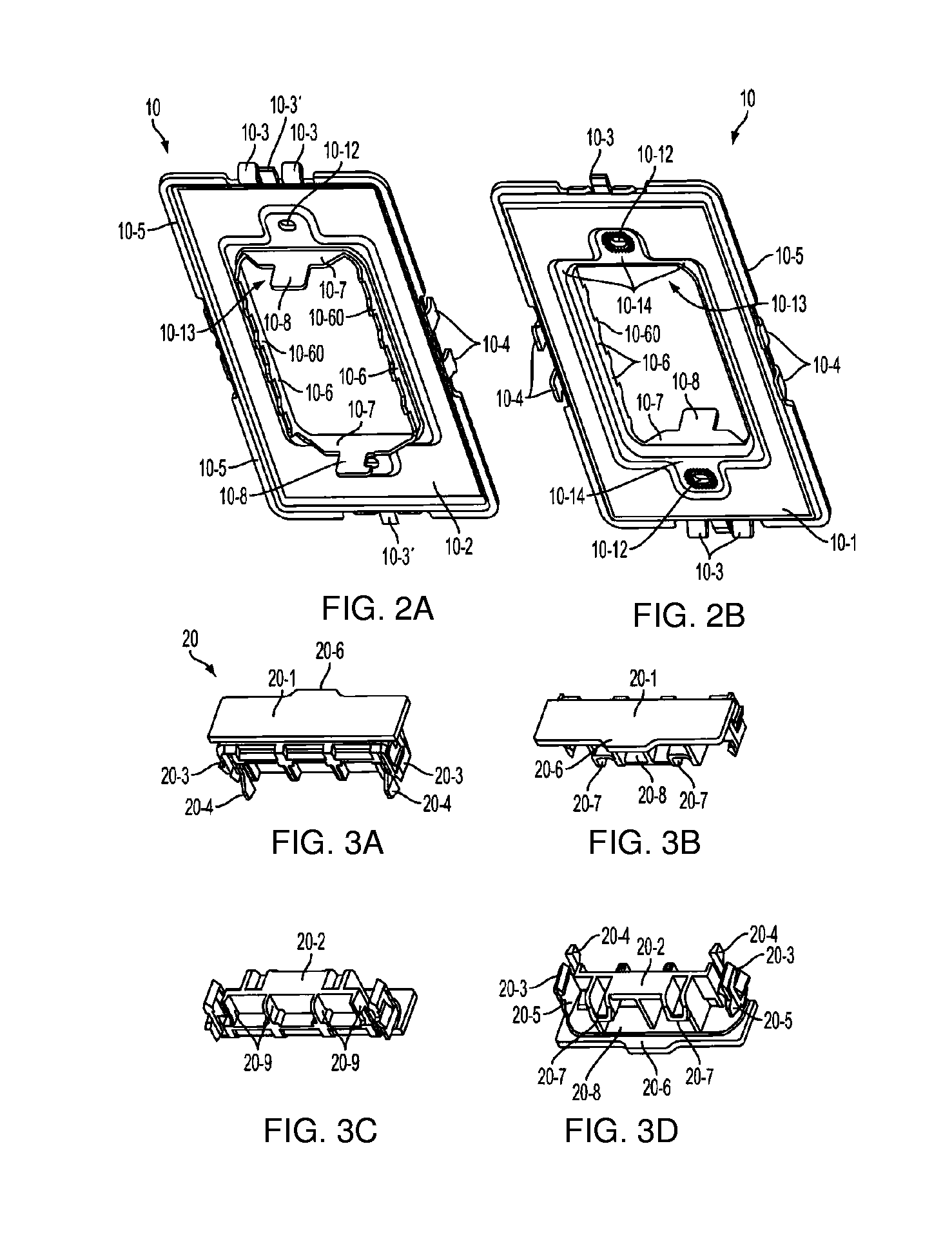
[0038]As embodied herein, and depicted in FIGS. 2A-2B, perspective views of a frame member 10 in accordance with the present invention are disclosed. FIG. 2A is directed to the rear side 10-2 of the frame member 10, whereas FIG. 2B is directed to the front side 10-1 of the frame member 10. The frame member 10 is configured to “complete the electrical enclosure” when one or more modular electrical devices (30, 40 or 50) and / or modular alignment connectors 20 are properly installed within the frame opening 10-13 such that the device wall box interior is substantial...


PUM


Abstract

The present invention is directed to a switch device that includes a first switch portion that is configured to rotate a first angular amount in a first direction about a first fixed axis of rotation and has a first pivot arm length. The first and second switch are coupled to the interface portion. The second switch portion rotates a second angular amount in a second direction and has a second pivot arm length. The second angular amount is greater than the first angular amount and a function of the first pivot arm length and the second pivot arm length. A set of switch contacts includes at least one fixed contact and a movable contact separated by a predetermined minimum distance that is a function of the first pivot arm length and the second pivot arm length.

Description

CROSS-REFERENCE TO RELATED APPLICATIONS[0001]This is application is a continuation-in-part of U.S. patent application Ser. No. 13 / 680,675 filed on Nov. 19, 2012, the content of which is relied upon and incorporated herein by reference in its entirety, and the benefit of priority under 35 U.S.C. §120 is hereby claimed.BACKGROUND OF THE INVENTION[0002]1. Field of the Invention[0003]The present invention relates generally to switching devices, and particularly to electromechanical switching devices.[0004]2. Technical Background[0005]A single pole single throw (SPST) switch is an electrical device that is an ON / OFF switch in that it either allows current to flow through a circuit or it interrupts that current flow. Wall switches are often configured as SPST switches that are used to turn electrical loads (such as lights) ON or OFF. Thus, when a person enters a darkened room they actuate the switch to turn the lights ON, and when they leave that room, they turn the lights OFF.[0006]A sin...

Claims


Application Information

Patent Timeline
IPC IPC(8): H01H23/16
CPCH01H23/168H02G3/12
Inventor SAVICKI, JR., GERALD R.ROHMER, RICHARD M.
Owner PASS SEYMOUR
Learn More