Vehicle body structure and method for assembling vehicle body structure

a vehicle body and vehicle body technology, applied in the direction of roofs, superstructures, transportation and packaging, etc., can solve the problems of low workability in assembly, reduced forces for reducing vibration and noise generated during driving of the vehicle, and low automation of assembling work, so as to achieve satisfactory workability during assembly, adequate strength and stiffness, and easy automatic assembling work

Active Publication Date: 2014-05-22
HONDA MOTOR CO LTD
View PDF41 Cites 32 Cited by
  • Summary
  • Abstract
  • Description
  • Claims
  • Application Information

AI Technical Summary

Benefits of technology

[0049]According to the present invention, a vehicle body structure and a method for assembling a vehicle body structure is provided, which have the workability during assembly satisfactory, the automatization of assembling work easy, and further, strength and stiffness adequately ensured.

Problems solved by technology

Accordingly, the roof arch 130 needs to be carried onto the narrow vehicle interior side to be attached, which makes the workability in assembling low, and makes automatization of assembling work difficult.
However, in the invention disclosed by Patent Document 1, as there are portions with a crushed cross-sectional shape, strength and stiffness are decreased, which causes problems that forces for reducing vibration and noises generated during driving of the vehicle are decreased, or the distortion amount of the vehicle body increases when lateral collision, rollover (overturn), or the like has occurred.

Method used


Image

  • Vehicle body structure and method for assembling vehicle body structure
  • Vehicle body structure and method for assembling vehicle body structure
  • Vehicle body structure and method for assembling vehicle body structure

Examples


Embodiment Construction

[0065]An embodiment according to the present invention will be described below in detail, referring to the drawings. In the description, the same reference symbols will be assigned to the same elements, and redundant description will be omitted.

[0066]In representing directions in the following description, the front, rear, left, right, upper, or lower side of a vehicle will be referred to. Incidentally, ‘vehicle-transversal direction’ and ‘left or right direction’ means the same.

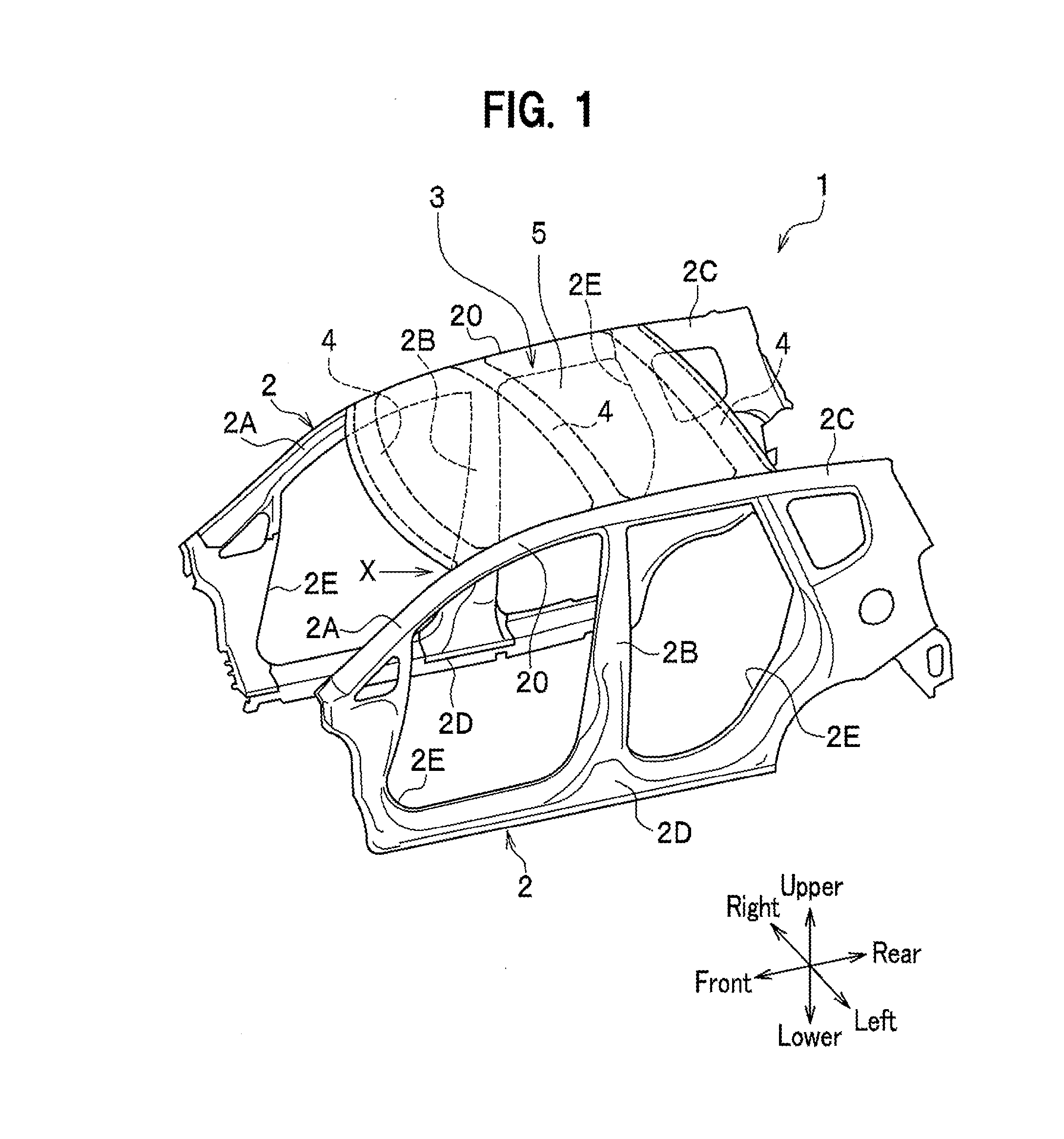
[0067]FIG. 1 is a schematic perspective view of a vehicle body structure 1 in an embodiment.

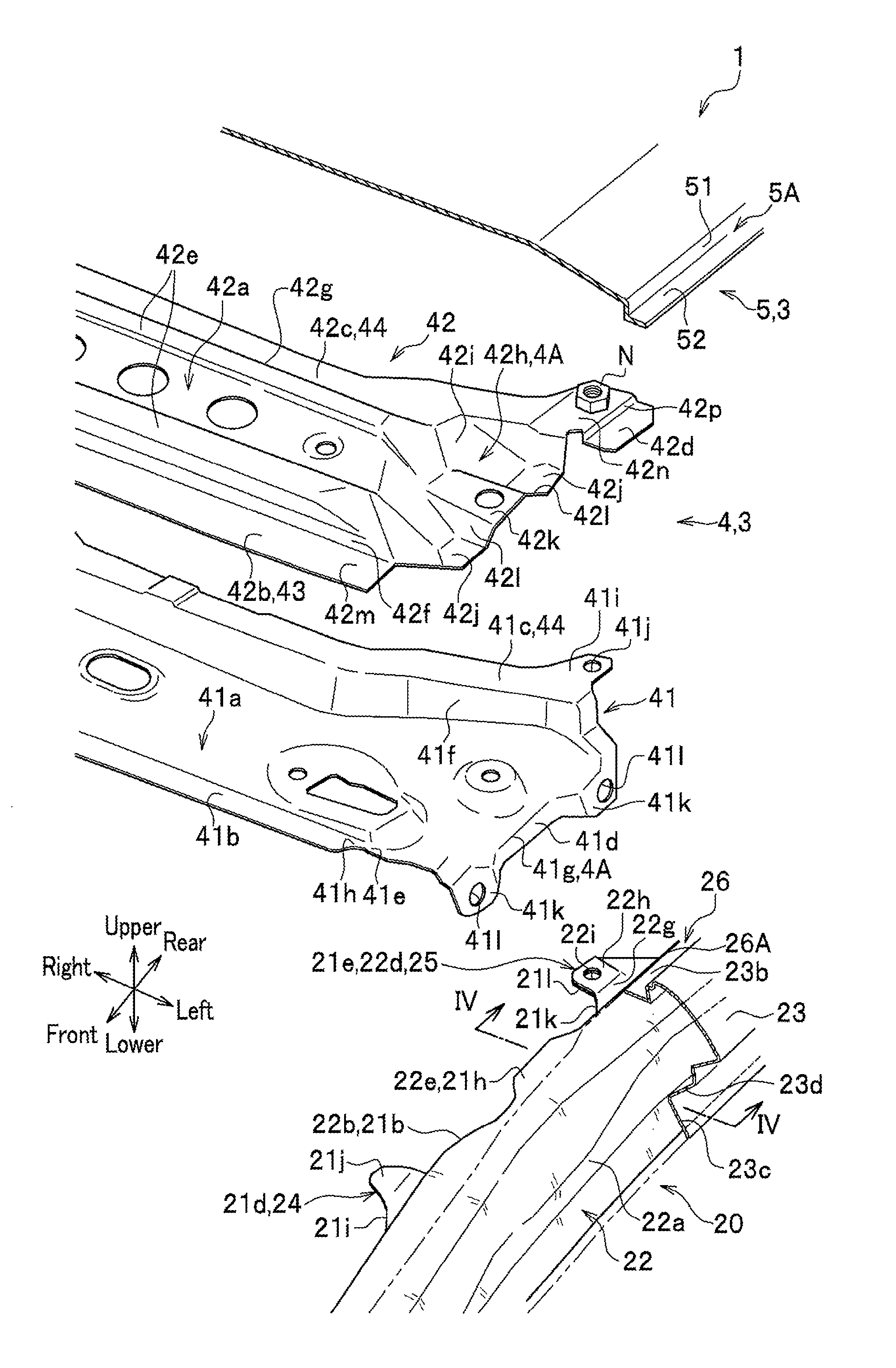
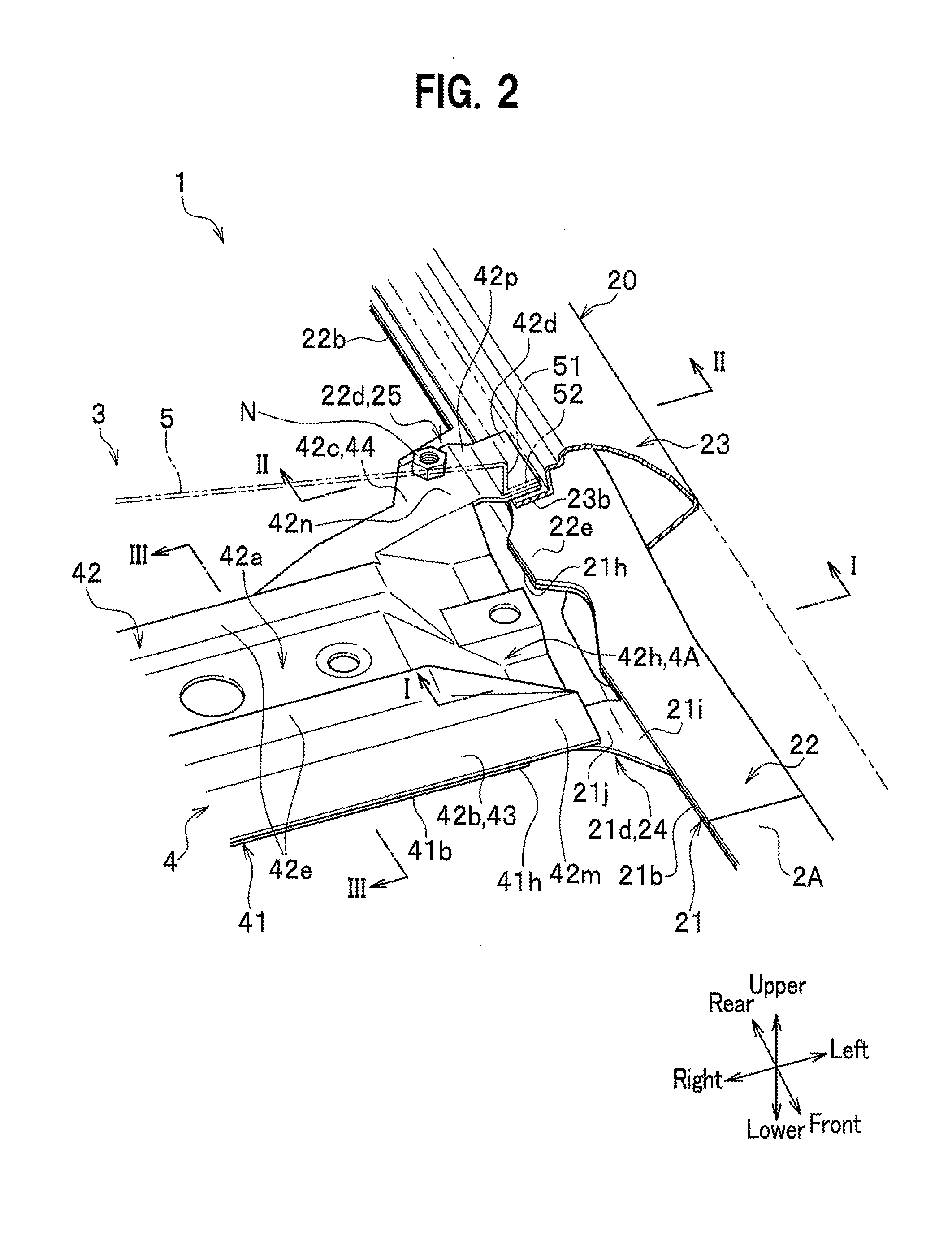
[0068]As shown in FIG. 1, the vehicle body structure 1 in the present embodiment is a structure for connecting a pair of side components 2, 2, which are provided on the left and right sides of a vehicle body to form the lateral side portions of the vehicle body, and a roof component 3, which forms the upper portion of the vehicle body.

[0069]Incidentally, as the side components 2, 2 are bilaterally symmetric, only the ...


PUM

PropertyMeasurementUnit
strengthaaaaaaaaaa
stiffnessaaaaaaaaaa
workabilityaaaaaaaaaa

Abstract

A vehicle body structure includes a roof side rail, roof arch, and roof panel. The roof side rail includes a mount portion extending inward in a vehicle-transversal direction and having a vehicle-transversally outer end portion of the roof panel mounted thereto. The roof arch includes a vehicle-transversally outer end portion that is located outside a vehicle-transversally inner end of the mount portion in the vehicle-transversal direction, joined with the roof side rail, and disposed at a position that is spaced apart downward from the vehicle-transversally outer end portion of the roof panel. At least one of the roof arch and the roof side rail includes a flange portion that extends toward the other one of the roof arch and the side rail and comes into contact with the other one of the roof arch and the roof side rail to restrict downward movement of the roof arch.

Description

TECHNICAL FIELD[0001]The present invention relates to a vehicle body structure and a method for assembling a vehicle body structure.BACKGROUND ART[0002]Conventionally, a roof panel forming the upper surface of a vehicle body is arranged between a pair of side components that are provided on the left side and the right side of the vehicle body and form the sides portions of the vehicle body, and roof arches are arranged to reinforce the upper portion of the vehicle body, the upper portion including the roof panel.[0003]FIG. 14A is a partial vertical cross-sectional view of a vehicle body structure in a conventional example in Patent Document 1, with a cut in the vehicle-transversal direction, and FIG. 14B is a partial vertical cross-sectional view of the vehicle body structure disclosed by Patent Document 1, with a cut in the vehicle-transversal direction.[0004]For example, as shown in FIG. 14A, an invention is taken as a conventional example in Patent Document 1, wherein a side comp...

Claims


Application Information

Patent Timeline
Patent Type & Authority Applications(United States)
IPC IPC(8): B62D25/06B62D65/02
CPCB62D65/02B62D25/06B62D25/02Y10T29/49622B62D33/0222
Inventor KISAKU, MASANORIOCHIAI, KATSUMINAGAI, YUKIHIKO
Owner HONDA MOTOR CO LTD
Why Eureka
Try Eureka