System and method for providing front-oriented visual information to vehicle driver

a technology for providing front-oriented visual information and vehicle drivers, which is applied in the field of visual displays, can solve the problems of numerous accidents, vehicle hazards in performing these maneuvers, etc., and achieve the effects of minimizing hazards, avoiding camera damage and/or restricted field of view, and improving safety

Inactive Publication Date: 2014-05-22
KLEAR VIEW CAMERA
View PDF12 Cites 34 Cited by
  • Summary
  • Abstract
  • Description
  • Claims
  • Application Information

AI Technical Summary

Benefits of technology

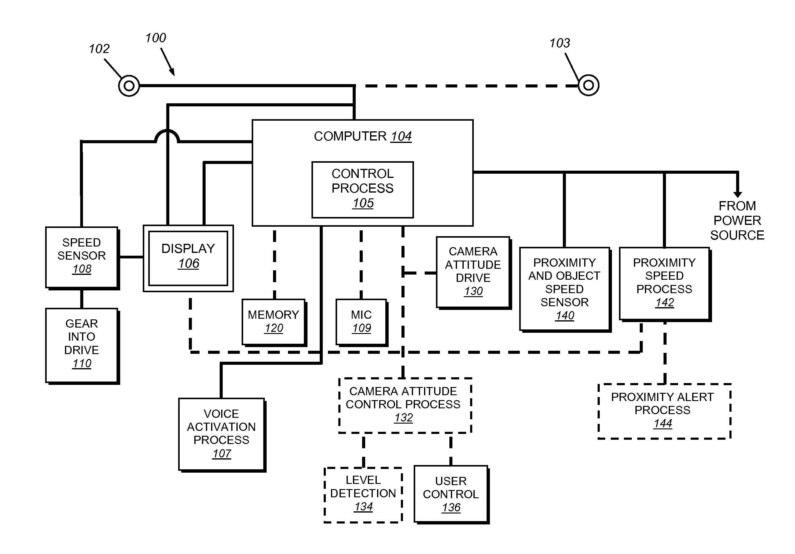
[0007]This system advantageously improves safety for vehicles moving into a line of traffic (turn) from a position that is perpendicular to the flow of that traffic and that are pulling out of a side street, building, garage or parking spot (merge). Often, such vehicles face hazards in performing these maneuvers because the driver must pull far enough forward to visually observe the near lane of traffic from his or her vantage point—which is typically several feet behind the front end of the vehicle. Illustratively, a protrusion of 4-6 feet or more is desirable in order for the driver to view the lane and determine whether to proceed or wait. During the movement to the protruded position, the front end of the car is vulnerable to being struck by other vehicles that are unseen to the driver, resulting in numerous accidents. The illustrative system and method provides a flush-mount camera at the specific location on the vehicle to minimize this hazard by transmitting an image of the scene of oncoming traffic to the driver from a vantage point that is essentially as far forward as possible.
[0008]Illustratively, the camera is located in and is flush

Problems solved by technology

Often, such vehicles face hazards in performing these maneuvers because the driver must pull far enough forward to visually observe the near lane of traffic from his or her vantage point—which is typically several feet

Method used


Image

  • System and method for providing front-oriented visual information to vehicle driver
  • System and method for providing front-oriented visual information to vehicle driver
  • System and method for providing front-oriented visual information to vehicle driver

Examples


Embodiment Construction

[0024]When a motor vehicle driver is situated so as to be perpendicular to the flow of traffic and pulling out of a side street, building, garage or parking spot, there is a danger to that driver and other operators. In order to see traffic in the oncoming lane, the driver has to pull far enough forward to visually observe the near lane of traffic. Other vehicles and objects placed along a roadway and other obstructions can prevent a clear view and necessitate a driver pulling forward into the near lane. Given that most vehicles have a front end that includes a motor or a storage compartment with a length of about 2-4 feet and that a driver typically sits another 2 feet or more from the dashboard, a protrusion of 4-6 feet or more is desirable in order for the driver to view the lane and determine whether to proceed or wait. During the movement to the protruded position, the front end of the car is vulnerable to being struck by other vehicles that are unseen to the driver. This resul...


PUM


Abstract

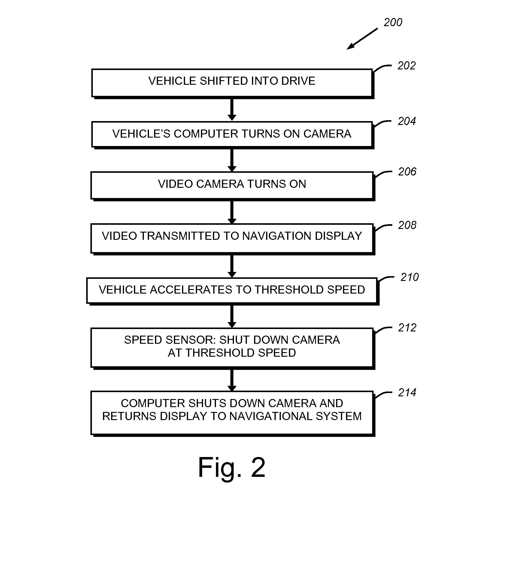
This invention provides a camera system installed on the front end of a vehicle, either on the left front, the right front, or both sides, that prevents accidents resulting from the driver's propensity to protrude into oncoming traffic to view that traffic. The camera is linked via wired or wireless connection to an onboard computer and a commercially available navigation display that is placed within the passenger compartment of the vehicle. The driver reviews a visual description on the display of any oncoming traffic in the form of motor vehicles, pedestrians, cyclists, animals and the like on the navigation display via a single screen, split screen or alternating screens. The camera system is furnished with a speed sensor that detects when the vehicle reaches a threshold speed of 3 miles per hour to activate or de-activate the camera. This camera system can be retrofitted into older vehicles.

Description

RELATED APPLICATION[0001]This application claims the benefit of U.S. Provisional Application Ser. No. 61 / 592,505, filed Jan. 30, 2012, entitled A FRONT LEFT VEHICLE CAMERA ALLOWING SAFETY PULLING OUT SHOWING ONSCREEN VISUAL TO DRIVER, the entire disclosure of which is herein incorporated by reference.FIELD OF THE INVENTION[0002]This invention relates to vehicle safety devices, and more particularly to visual displays that enhance vehicle safety.BACKGROUND OF THE INVENTION[0003]Each year, thousands of people die or are badly injured in automobile accidents. One situation that causes needless accidental deaths and injury arises when a car moves into a street or motorway from a position that is perpendicular to the axis of that street or motorway. This can occur when a vehicle is moving out of a street, parking garage or parking space. Drivers pulling in to oncoming traffic from such a position must begin by placing the front end of their vehicle far enough out into the street that the...

Claims


Application Information

Patent Timeline
IPC IPC(8): H04N7/18
CPCB60R1/00B60R2300/302B60R2300/404B60R2300/406B60R2300/605B60R2300/802B60K2370/152B60K2370/168B60K2370/176B60K2370/193B60K2370/52B60K2370/21B60K2370/179B60K35/00B60Q9/008B60R2300/105B60R2300/303B60R2300/70G01C21/3697
Inventor PETRILLO, STEVENROEGER, ROBERT MICHAEL
Owner KLEAR VIEW CAMERA
Why Eureka
Try Eureka