Image Pickup Lens And Image Pickup Device

a pickup device and image technology, applied in the field of compact image pickup lenses, can solve the problems of insufficient correction of chromatic aberration, inability to expect to obtain an image pickup device of high performance, and difficulty in achieving a sufficient reduction in the size of the image pickup lens and the image pickup device, and achieve excellent formability and suppress shading

Inactive Publication Date: 2014-05-22
KONICA MINOLTA INC
View PDF1 Cites 6 Cited by
  • Summary
  • Abstract
  • Description
  • Claims
  • Application Information

AI Technical Summary

Benefits of technology

[0016]An object of the present invention is to provide an image pickup lens for forming an image on a solid-state image sensor having the curved image pickup surface, the image pickup lens being compact and high-performance, capable of suppressing shading, including lenses having excellent formability, and having a brightness or speed of about, for example, F2.8 to F4.

Problems solved by technology
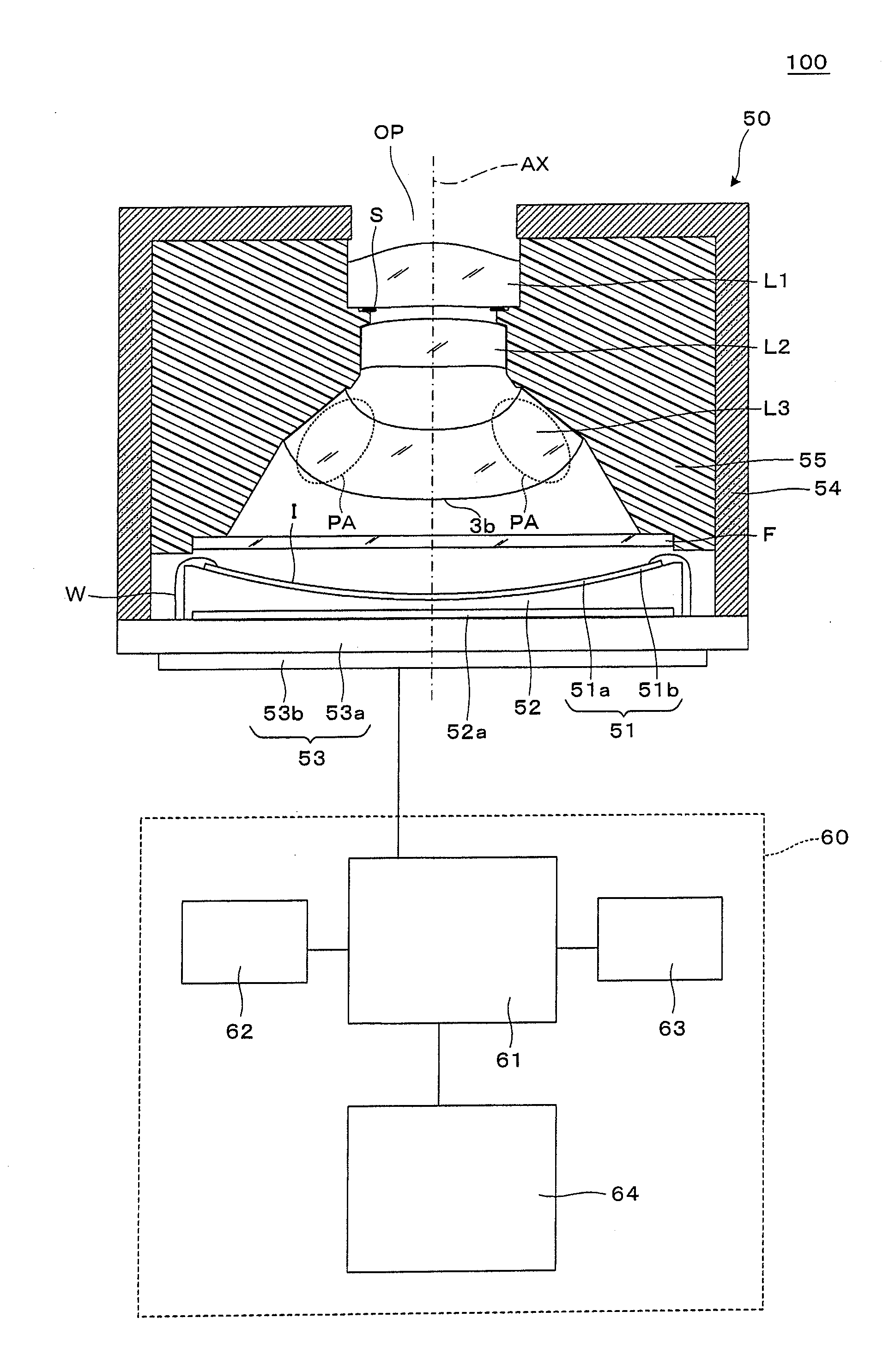
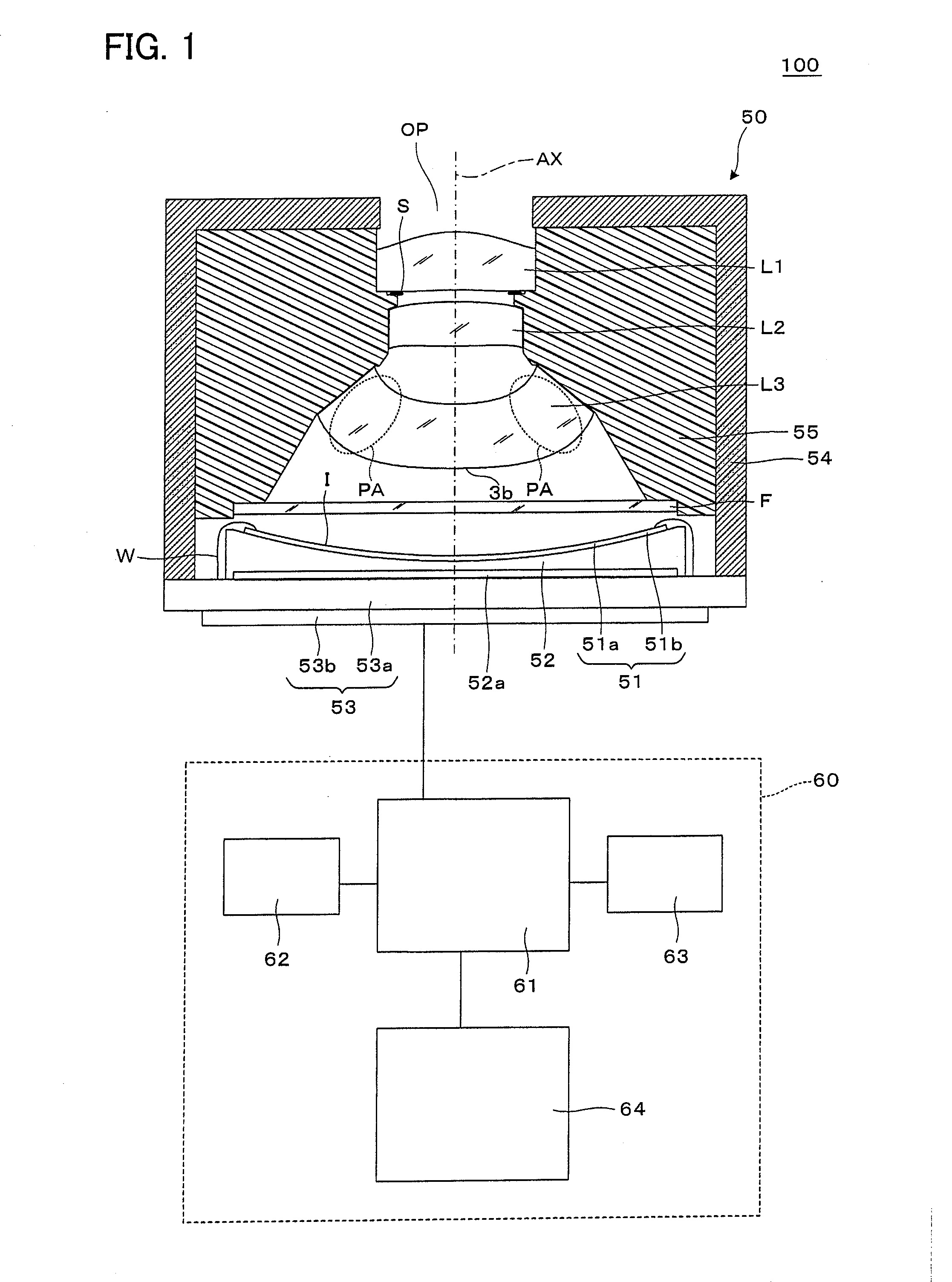
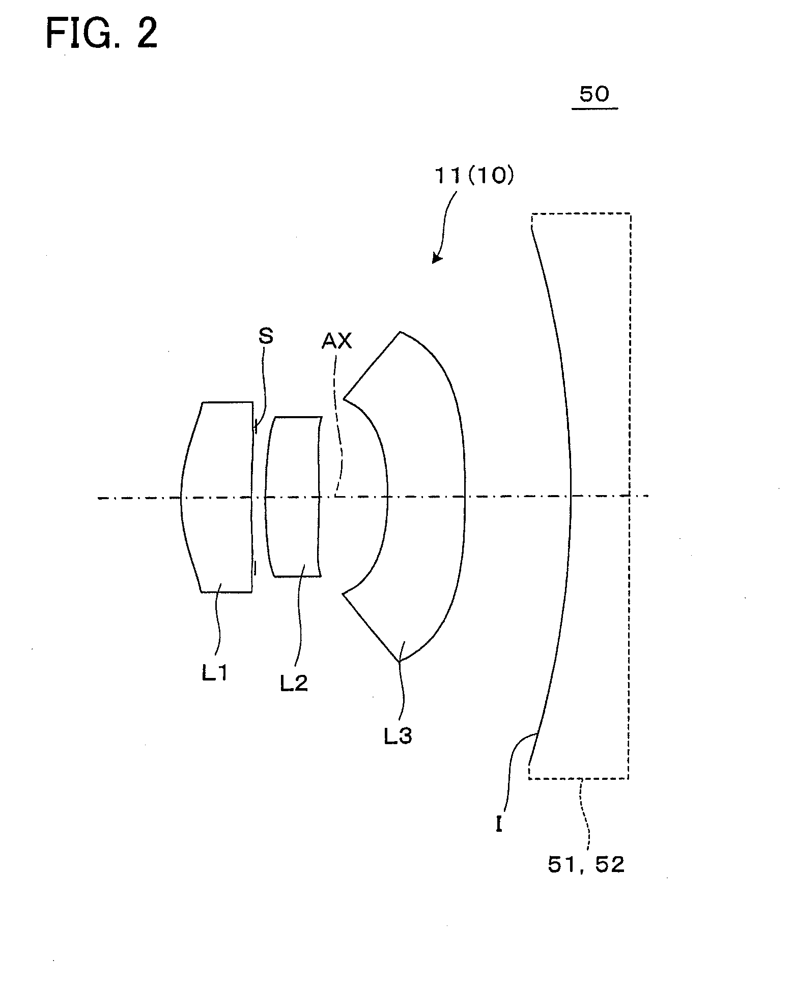
However, the solid-state image sensor has the CIF size (352 pixels×288 pixels) and the image pickup lens has a single-lens configuration, and therefore, the chromatic aberration is not corrected sufficiently and it is not possible to expect to obtain an image pickup device of high performance by using a solid-state image sensor having a more number of pixels.
In Patent Literature 2, with a two-lens configuration, improvement of performance and a reduction in size to a certain degree are achieved, but, the back focus is long and in some lenses, the image side surface of the lens nearest to the image to side tilts toward the image side on the periphery, and therefore, it is difficult to achieve a sufficient reduction in size of the image pickup lens and the image pickup device while securing a clearance between the image pickup lens and the solid-state image sensor.
However, the F-number of each of the image pickup lenses in Patent Literatures 3 to 5 is large or corresponds slow and if the F-number is attempted to be decreased or fast, it is not possible to obtain a sufficient performance, and the back focus is long, therefore, the image pickup lens and the image pickup device increase in size.
Because of this, an excellent performance can be obtained in the long-side direction of the image area, but, the image pickup surface remains a flat surface in the short-side direction of the image area or picture plane, and therefore, it is not possible to make an attempt to improve performance and further, there may be a case where a reduction in image quality is caused depending on the correction situation of the curvature of field.
That is, by curving the image pickup surface only in the long-side direction as in Patent Literatures 3 to 5, it is difficult to obtain a high performance across the entire image area.
Because of this, in general, the F-number is made slow or large and the focal depth is set great so that blurring in the planar direction is not conspicuous, and therefore, it has been difficult to decrease the F-number.
Further, those disclosed in Patent Literatures 3 to 5 are the image pickup lenses for the film camera as described previously, and therefore the principal ray incidence angle is not necessarily designed to be sufficiently small on the periphery of the image pickup surface.
However, if the periphery has a positive refractive power, the lens tends to have a large ratio between the thickness at the center part of the lens and that on the periphery, that is, a so-called center-to-periphery thickness ratio, and there is a possibility that the formability is impaired if the center-to-periphery thickness ratio is large like this.
However, the image pickup lens described in Patent Literature 3 has a large F-number of about F10, a long back focus, and a large size, and the telecentric characteristics thereof are not sufficiently excellent, and therefore, it can be thought that the application of the image pickup lens to a compact image pickup device using a solid-state image sensor is difficult.

Method used


Image

  • Image Pickup Lens And Image Pickup Device
  • Image Pickup Lens And Image Pickup Device
  • Image Pickup Lens And Image Pickup Device

Examples


example 1

[0111]General specifications of an image pickup lens of Example 1 are as follows.

f=2.38 mm

fB=0.76 mm

F=2.4

2Y=3.5 mm

ENTP=0.41 mm

EXTP=−1.07 mm

H1=−0.31 mm

H2=−1.63 mm

[0112]Lens surface data of Example 1 is shown in Table 1 below. “STOP” means the aperture stop S and “IMAG” means the image pickup surface I.

TABLE 1SurfaceEffectivenumberR (mm)D (mm)Ndvdradius (mm)1*1.1610.491.5447056.20.662*4.2220.030.473 infinity0.070.45(STOP)4*3.7880.371.5447056.20.485*−6.6890.480.556*−1.9100.541.6347023.90.687*−5.9780.741.158 −6.354(IMAG)Aspherical surface coefficients of the lens surfaces of Example1 are as follows.First surfaceK = −0.25843E+01,A4 = 0.45319E−01,A6 = −0.20599E+00,A8 = −0.68537E+00,A10 = 0.55464E+00Second surfaceK = −0.30000E+02,A4 = −0.21862E+00,A6 = −0.77470E+00,A8 = 0.21693E+01,A10 = −0.14820E+01Fourth surfaceK = 0.15140E+02,A4 = 0.32865E−01,A6 = −0.31885E+00,A8 = 0.40411E+01,A10 = −0.38145E+01Fifth surfaceK = −0.30000E+02,A4 = 0.11738E+00,A6 = 0.87909E+00,A8 = −0.25596E+01,A10 = 0.946...

example 2

[0116]General specifications of an image pickup lens of Example 2 are as follows.

f=2.39 mm

fB=0.6 mm

F=2.4

2Y=3.5 mm

ENTP=0.44 mm

EXTP=−1.26 mm

H1=−0.23 mm

H2=−1.78 mm

[0117]Lens surface data of Example 2 is shown in Table 3 below.

TABLE 3SurfaceEffectivenumberR (mm)D (mm)Ndvdradius (mm)1*1.1910.481.5447056.20.682*2.3150.050.463 infinity0.070.44(STOP)4*2.0150.451.5447056.20.505*−5.0960.380.606*−2.0100.901.6347023.90.657*−9.5700.601.328 −6.969(IMAG)Aspherical surface coefficients of the lens surfaces of Example2 are as follow.First surfaceK = −0.23484E+01,A4 = 0.62251E−01,A6 = −0.11697E+00,A8 =−0.39497E+00,A10 = 0.19543E+00Second surfaceK = −0.41745E+01,A4 = −0.11680E+00,A6 = −0.65316E+00,A8 = 0.91685E+00,A10 = −0.75003E+00Fourth surfaceK = 0.45036E+01,A4 = −0.67987E−01,A6 = −0.42921E+00,A8 = 0.97000E+00,A10 = −0.76215E+00Fifth surfaceK = −0.30000E+02,A4 = −0.93881E−01,A6 = 0.38334E+00,A8 = −0.22038E+01,A10 = 0.35467E+01Sixth surfaceK = −0.39257E+01,A4 = −0.55727E+00,A6 = 0.50788E+00,A8 = −0....

example 3

[0121]General specifications of an image pickup lens of Example 3 are as follows.

f=3 mm

fB=1.73 mm

F=2.8

2Y=4.536 mm

ENTP=0 mm

EXTP=−1.71 mm

H1=0.38 mm

H2=−1.27 mm

[0122]Lens surface data of Example 3 is shown in Table 5 below.

TABLE 5SurfaceEffectivenumberR (mm)D (mm)Ndvdradius (mm)1 infinity−0.060.53STOP2*1.2180.651.5447056.20.563*2.1070.600.654*−801.6790.611.5447056.21.035*−3.2481.721.336 −6.893(IMAG)Aspherical surface coefficients of the lens surfaces of Example3 are as follow.Second surface K = −0.83589E−01, A4 = 0.63341E−02,A6 = 0.17877E+00, A8 = −0.62056E+00, A10 = 0.16155E+01, A12 = −0.18854E+01 Third surface K = 0.43853E+01, A4 = 0.72575E−01, A6 = −0.65234E−02, A8 = −0.10661E+00, A10 = 0.80743E+00, A12 = −0.73994E+00 Fourth surface K = −0.94483E+05, A4 = 0.30860E−01, A6 = −0.10667E+00, A8 = 0.14926E+00,A10 = −0.23616E+00, A12 = 0.18440E+00, A14 = −0.66932E−01 Fifth surface K = −0.34691E+02,A4 = −0.44080E−01, A6 = 0.55225E−01, A8 = −0.22438E−01, A10 = −0.25165E−01, A12 = 0.21006E−01,...


PUM


Abstract

An image pickup lens 10 includes a first lens L1, a second lens L2, and a third lens L3. An image pickup surface I of a solid-state image sensor 51 is curved into the shape of a shallow concave spherical surface. By forming an image side surface 3b of the third lens L3, which is the lens nearest to the image side, into an aspherical shape, it is possible to make a curvature of field suitable to the curved image pickup surface I while securing excellent telecentric characteristics. The above image pickup lens 10 satisfies conditional expression (1) where THID is a thickness of an outermost periphery PA of the lens L3 nearest to the image side along an optical axis direction AX and THIC is a thickness of the lens L3 nearest to the image side on the optical axis AX.

Description

TECHNICAL FIELD[0001]The present invention relates to a compact image pickup lens for forming an image on a solid-state image sensor having a curved image pickup surface, and an image pickup device including the same.BACKGROUND ART[0002]Recently, a compact image pickup device using a solid-state image sensor, such as a CCD (Charge Coupled Device) type image sensor and a CMOS (Complementary Metal Oxide Semiconductor) type image sensor, is mounted on a mobile terminal, such as a mobile telephone and a PDA (Personal Digital Assistant), and further, on a notebook personal computer, etc., and it is made possible to transmit image information, not only audio information, to and from a remote site.[0003]For the solid-state image sensor used in such an image pickup device, a reduction in pixel size is in progress and an attempt is made to increase the number of pixels and to reduce the size of the image sensor. Further, it is made possible to curve the image pickup surface (for example, see...

Claims


Application Information

Patent Timeline
Patent Type & Authority Applications(United States)
IPC IPC(8): G02B13/00H04N5/335
CPCG02B13/18G02B13/0035H04N25/00G02B13/002
Inventor SANO, EIGO
Owner KONICA MINOLTA INC
Why Eureka
Try Eureka