Power control method, base station and terminal equipment

a power control and terminal technology, applied in the field of communication, can solve the problems of increasing signaling overhead and deteriorating the service quality of the terminal in the macro cell, and achieve the effect of reducing signaling overhead and avoiding the degradation of the service quality of the terminal

Inactive Publication Date: 2014-05-29
FUJITSU LTD
View PDF24 Cites 23 Cited by
  • Summary
  • Abstract
  • Description
  • Claims
  • Application Information

AI Technical Summary

Benefits of technology

[0008]An aspect of embodiments of the present invention is to provide a power control method, a base station and terminal equipment. With the method, multiple processes of detection are not needed, which reduces signaling overhead, avoids the degradation of the service quality of a terminal in the macro cell, and solves the problem in the relevant art.

Problems solved by technology

It was found by the inventors in the implementation of the present invention that a defect exists in an existing method: multiple processes of detection are needed, which increases signaling overhead, and time consumed in detection will result in degradation of service quality of a terminal in the macro cell.

Method used


Image

  • Power control method, base station and terminal equipment
  • Power control method, base station and terminal equipment
  • Power control method, base station and terminal equipment

Examples


embodiment 1

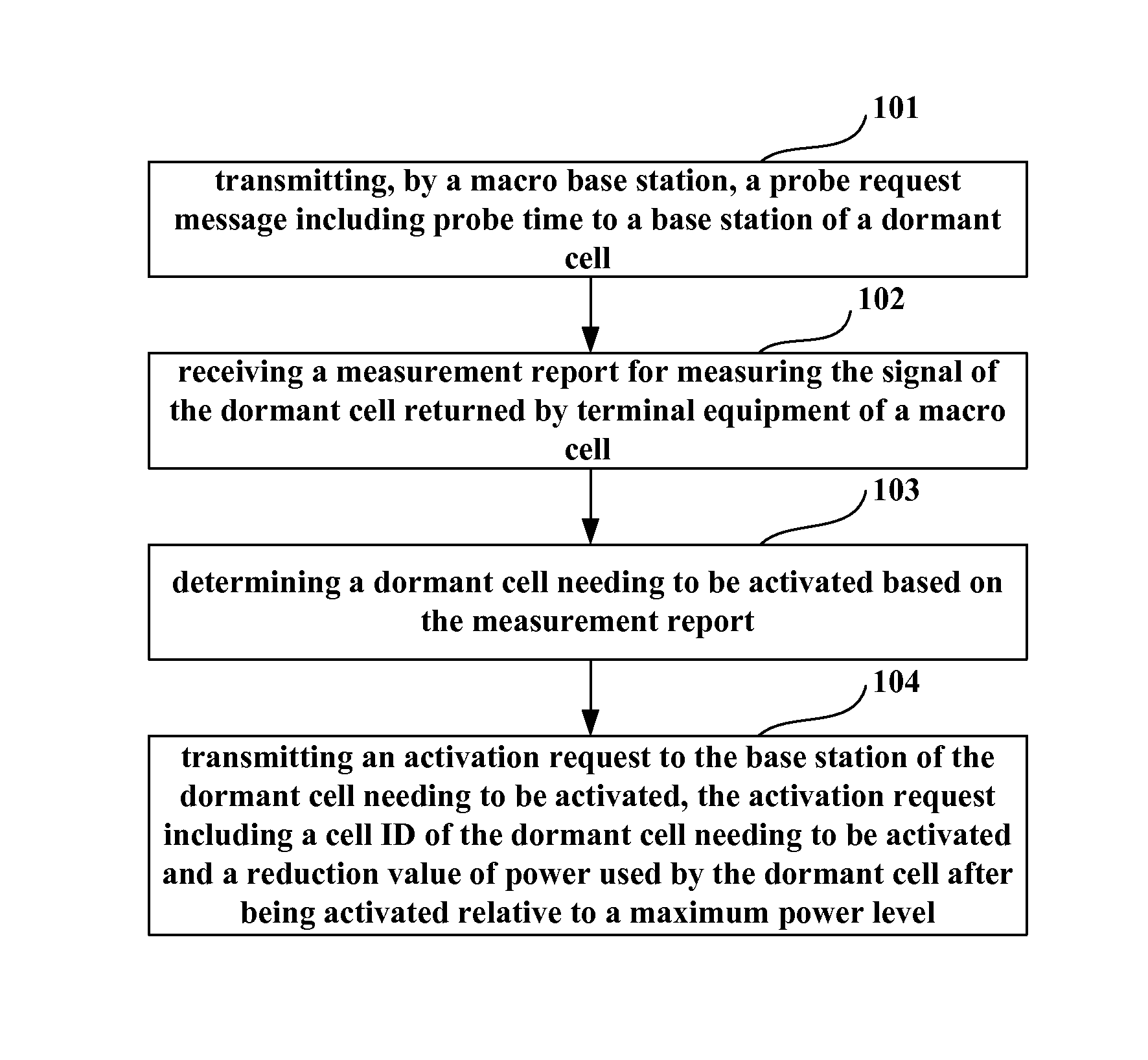
[0073]FIG. 1 is a schematic diagram of the power control method of Embodiment 1 of the present invention. As shown in FIG. 1, the method includes:

[0074]step 101: transmitting, by a macro base station, a probe request message including probe time to a base station of a dormant cell, so that the dormant cell transmits a signal at maximum power within the probe time;

[0075]step 102: receiving a measurement report for measuring the signal of the dormant cell returned by terminal equipment of a macro cell;

[0076]step 103: determining a dormant cell needing to be activated based on the measurement report; and

[0077]step 104: transmitting an activation request to the base station of the dormant cell needing to be activated, the activation request including a cell ID of the dormant cell needing to be activated and a reduction value ΔP1 of power used by the dormant cell after being activated relative to a maximum power level, so that the base station of the dormant cell transmits a signal at po...

embodiment 2

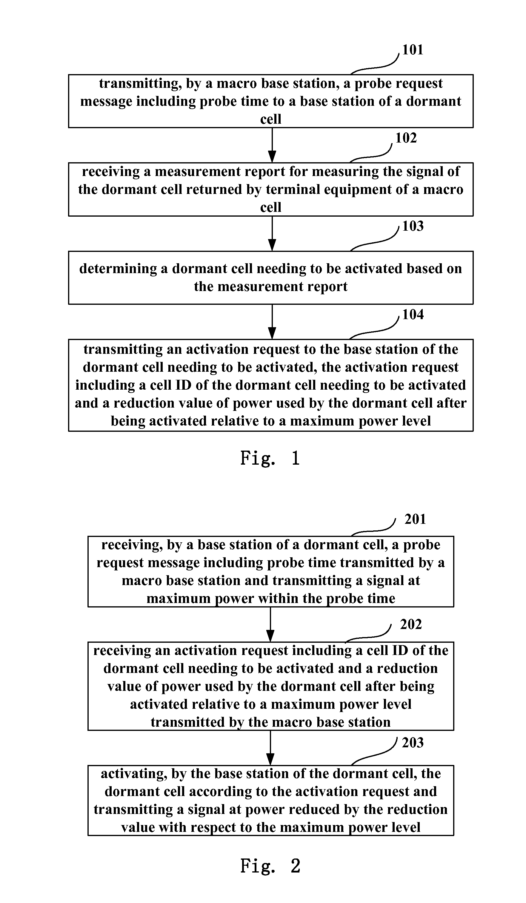
[0078]FIG. 2 is a flowchart of the power control method of Embodiment 2 of the present invention. As shown in FIG. 2, the method includes:

[0079]step 201: receiving, by a base station of a dormant cell, a probe request message including probe time transmitted by a macro base station and transmitting a signal at maximum power within the probe time;

[0080]step 202: receiving an activation request including a cell ID of the dormant cell needing to be activated and a reduction value ΔP1 of power used by the dormant cell after being activated relative to a maximum power level transmitted by the macro base station; and

[0081]step 203: activating, by the base station of the dormant cell, the dormant cell according to the activation request and transmitting a signal at power reduced by the reduction value ΔP1 with respect to the maximum power level.

[0082]It can be seen from the above embodiment that with the method, the base station of the dormant cell needs not to transmit a signal at maximum...

embodiment 3

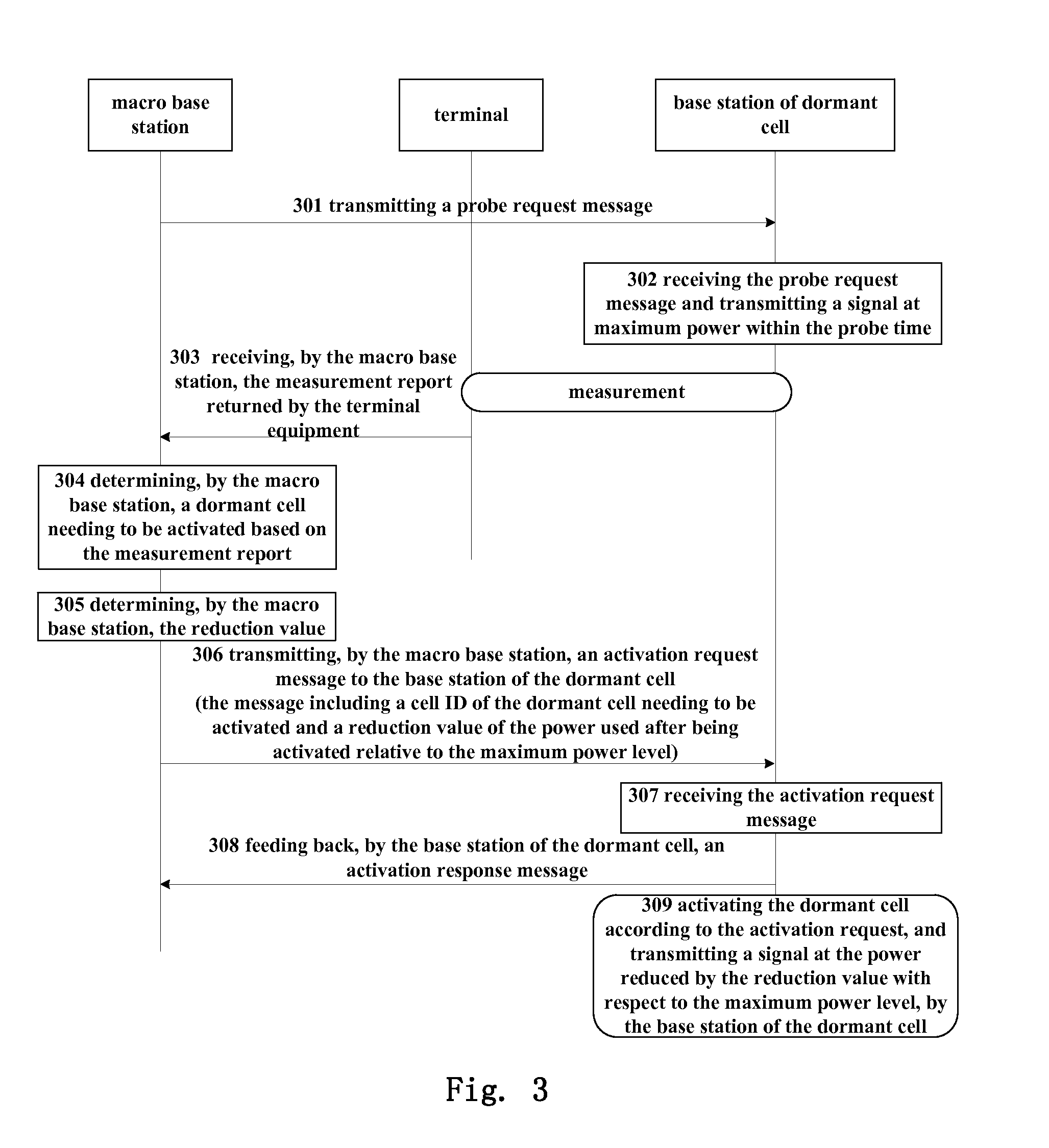
[0083]FIG. 3 is a flowchart of the power control method of Embodiment 3 of the present invention. As shown in FIG. 3, the method includes:

[0084]step 301: transmitting, by a macro base station, a probe request message including probe time to a base station of a dormant cell;

[0085]step 302: receiving, by the base station of the dormant cell, the probe request message including probe time transmitted by the macro base station, and transmitting a signal at maximum power within the probe time;

[0086]in this way, terminal equipment of the macro cell may measure a signal of the dormant cell within the probe time, and report a measurement result to the macro base station; wherein, the measurement result may include signal intensity (such as reference signal receiving power, RSRP), or signal quality (such as reference signal receiving quality, RSRQ), etc.;

[0087]step 303: receiving, by the macro base station, the measurement report for measuring the signal of the dormant cell returned by the t...


PUM


Abstract

A power control including: determining by a macro base station a dormant cell to be activated based on a measurement report; and transmitting an activation request to the base station of the dormant cell to be activated, the activation request including a cell ID of the dormant cell to be activated and a reduction value of the power used by the dormant cell after being activated relative to the maximum power level or an initial power level, a power increasing level and time duration of power or predetermined first time. The base station of the dormant cell transmits the signal at power reduced by the reduction value with respect to the maximum power after the dormant cell is activated or transmits the signal at the power that is increased step by step.

Description

CROSS-REFERENCE TO RELATED APPLICATIONS[0001]This is a continuation of International Application No. PCT / CN2011 / 078492, filed on Aug. 16, 2011, now pending, the contents of which are herein wholly incorporated by reference.TECHNICAL FIELD[0002]The present invention relates to the field of communications, and in particular to a power control method, a base station and terminal equipment.BACKGROUND[0003]In subjects of energy saving of a long-term evolution advanced (LTE-A) network, cells of a network may be divided into a macro cell and a capacity boosting cell; wherein, the macro cell provides basic network coverage, and the capacity boosting cell is activated to share part of a load of the macro cell when the load of the network is relatively high, and enters into a dormant state to reduce energy consumption when the load of the network is relatively low. A capacity boosting cell entering into a dormant state is hereinafter referred to as a dormant cell.[0004]In selecting dormant ce...

Claims


Application Information

Patent Timeline
Patent Type & Authority Applications(United States)
IPC IPC(8): H04W28/02H04W88/08
CPCH04W88/08H04W28/0205H04W52/0206H04W52/143H04W52/343H04W52/50Y02D30/70
Inventor WANG, WEIWEILI, ZHAOJUNLU, YANLINGXU, HAIBOZHOU, HUA
Owner FUJITSU LTD
Why Eureka
Try Eureka