
Image generation for collaborative sound systems

a sound system and image generation technology, applied in the field of multi-channel sound systems, can solve the problems of preventing consumers from adopting 5.1, 7.1 and higher-order surround sound systems, expensive av receivers and loudspeakers that need to reproduce convincing surround sound, and unsightly running of wires, so as to avoid or reduce costs, avoid the effect of cost and cost promotion

Active Publication Date: 2014-05-29
QUALCOMM INC
View PDF5 Cites 116 Cited by
  • Summary
  • Abstract
  • Description
  • Claims
  • Application Information

AI Technical Summary

Benefits of technology

The patent is about a device that allows mobile phones and other mobile devices to work together as a sound system. This means that users don't have to spend money on separate speakers, and the device can be placed in a way that allows for surround sound without needing to run cables or connect to a power source. This results in cost savings and more flexibility in how the system can be set up.

Problems solved by technology

Although surround sound may provide a more immersive listening (and, in conjunction with video, viewing) experience, the AV receiver and loudspeakers required to reproduce convincing surround sound are often expensive.
Running these wires may be unsightly and prevent adoption of 5.1, 7.1 and higher order surround sound systems by consumers.

Method used


Image

  • Image generation for collaborative sound systems
  • Image generation for collaborative sound systems
  • Image generation for collaborative sound systems

Examples


Embodiment Construction

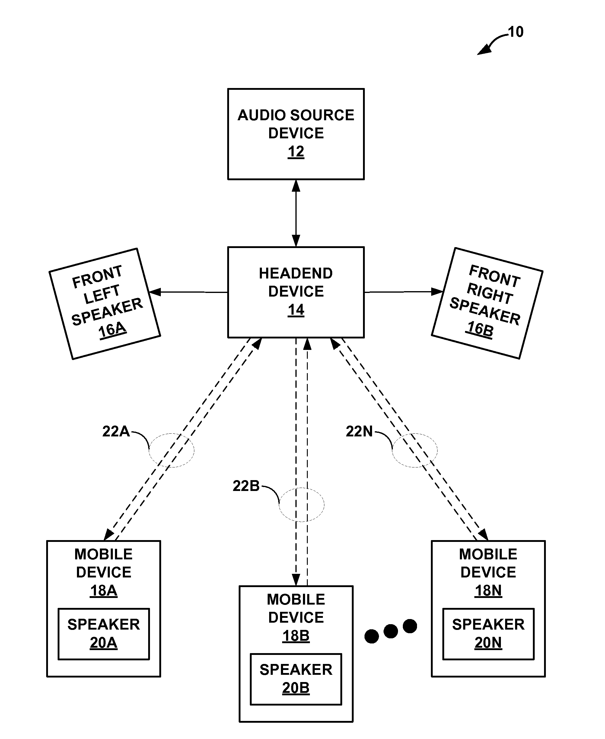
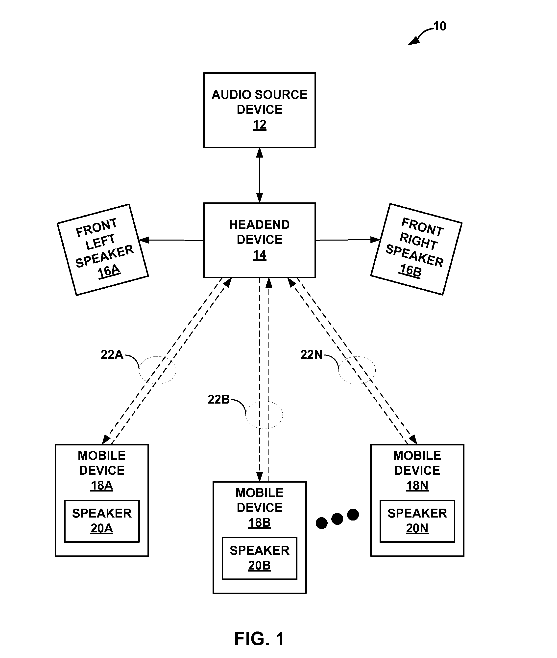
[0025]FIG. 1 is a block diagram illustrating an example collaborative surround sound system 10 formed in accordance with the techniques described in this disclosure. In the example of FIG. 1, the collaborative surround sound system 10 includes an audio source device 12, a headend device 14, a front left speaker 16A, a front right speaker 16B and mobile devices 18A-18N (“mobile devices 18”). While shown as including the dedicated front left speaker 16A and the dedicated front right speaker 16B, the techniques may be performed in instances where the mobile devices 18 are also used as front left, center and front right speakers. Accordingly, the techniques should not be limited to example the collaborative surround sound system 10 shown in the example of FIG. 1. Moreover, while described below with respect to the collaborative surround sound system 10, the techniques of this disclosure may be implemented by any form of sound system to provide a collaborative sound system.

[0026]The audi...


PUM


Abstract

In general, techniques are described for image generation for a collaborative sound system. A headend device comprising a processor may perform these techniques. The processor may be configured to determine a location of a mobile device participating in a collaborative surround sound system as a speaker of a plurality of speakers of the collaborative surround sound system. The processor may further be configured to generate an image that depicts the location of the mobile device that is participating in the collaborative surround sound system relative to the plurality of other speakers of the collaborative surround sound system.

Description

[0001]This application claims the benefit of U.S. Provisional Application No. 61 / 730,911, filed Nov. 28, 2012.TECHNICAL FIELD[0002]The disclosure relates to multi-channel sound system and, more particularly, collaborative multi-channel sound systems.BACKGROUND[0003]A typical multi-channel sound system (which may also be referred to as a “multi-channel surround sound system”) typically includes an audio / video (AV) receiver and two or more speakers. The AV receiver typically includes a number of outputs to interface with the speakers and a number of inputs to receive audio and / or video signals. Often, the audio and / or video signals are generated by various home theater or audio components, such as television sets, digital video disc (DVD) players, high-definition video players, game systems, record players, compact disc (CD) players, digital media players, set-top boxes (STBs), laptop computers, tablet computers and the like.[0004]While the AV receiver may process video signals to pro...

Claims


Application Information

Patent Timeline
Patent Type & Authority Applications(United States)
IPC IPC(8): H04R5/00
CPCH04R5/00H04R5/02H04R2205/024H04R2420/07H04S3/00H04S7/308H04S2400/13
Inventor KIM, LAE-HOONXIANG, PEI
Owner QUALCOMM INC
Learn More