
Dynamic electroacoustic transducer

Active Publication Date: 2014-05-29
SENNHEISER ELECTRONICS GMBH & CO KG
View PDF3 Cites 0 Cited by
  • Summary
  • Abstract
  • Description
  • Claims
  • Application Information

AI Technical Summary

Benefits of technology

The present invention provides a dynamic electroacoustic transducer with reduced susceptibility to diaphragm wobble and flutter. The invention addresses the issue of asymmetry in the oscillator system caused by the coil wires. The invention provides an improved symmetrical structure to reduce the tendency to wobble andflutter.

Problems solved by technology

In the case of dynamic electroacoustic transducers however it can happen that there is an asymmetry in the diaphragm and that can lead to unwanted wobbling of the diaphragm.

Method used


Image

  • Dynamic electroacoustic transducer
  • Dynamic electroacoustic transducer
  • Dynamic electroacoustic transducer

Examples


Embodiment Construction

[0019]It is to be understood that the figures and descriptions of the present invention have been simplified to illustrate elements that are relevant for a clear understanding of the present invention, while eliminating, for purposes of clarity, many other elements which are conventional in this art. Those of ordinary skill in the art will recognize that other elements are desirable for implementing the present invention. However, because such elements are well known in the art, and because they do not facilitate a better understanding of the present invention, a discussion of such elements is not provided herein.

[0020]The present invention will now be described in detail on the basis of exemplary embodiments.

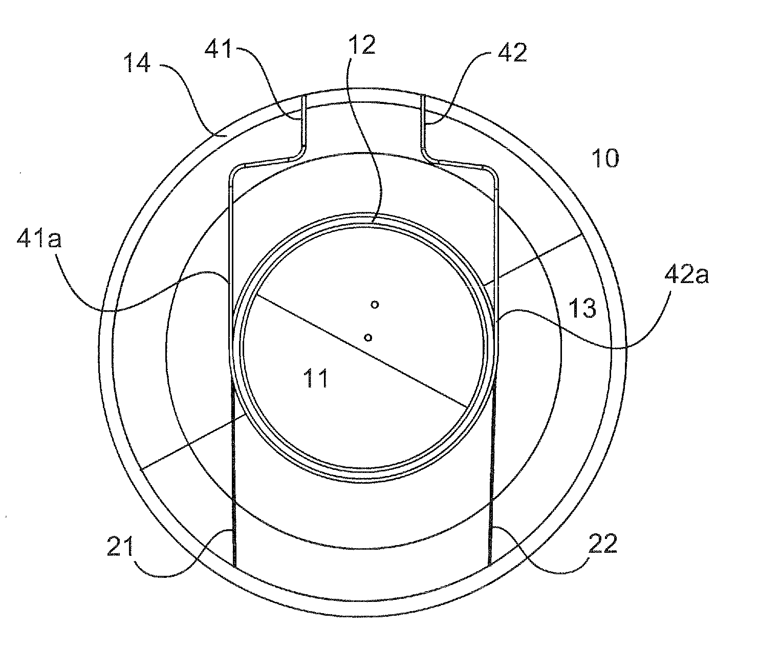
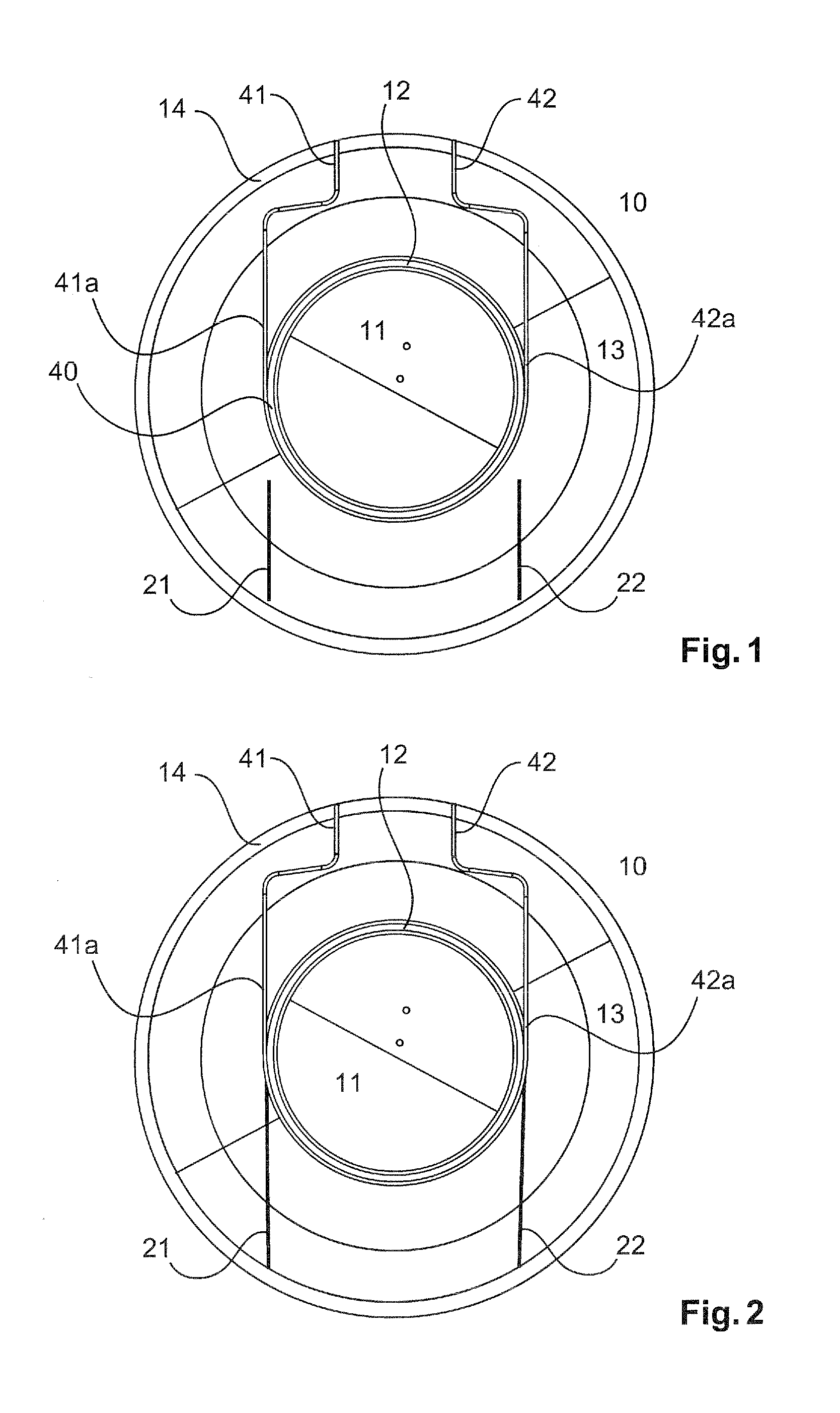
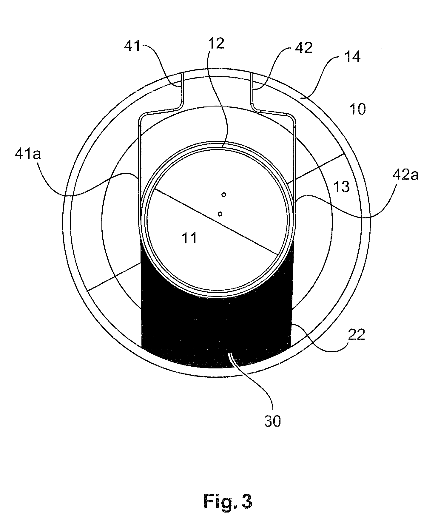
[0021]According to the invention the dynamic electroacoustic transducers have a magnet system with an air gap in which an oscillator coil can oscillate. The oscillator coil is connected with a first end to the diaphragm and the second end oscillates in the air gap.

[0022]FIG. 1 ...


PUM


Abstract

There is provided a dynamic electroacoustic transducer comprising a diaphragm and an oscillator coil which is fixed to the diaphragm in an oscillator coil portion. The diaphragm has a first portion within the oscillator coil portion and a second portion between the oscillator coil portion and an edge of the diaphragm. The diaphragm has at least one stiffening portion in the region of the second portion, which is of a different stiffness from the second portion of the diaphragm. The stiffening portion is of a such a configuration that a wobble movement of the diaphragm is substantially compensated.

Description

[0001]The present application claims priority from German Patent Application No. DE 10 2012 214 263.0 filed on Aug. 10, 2012, the disclosure of which is incorporated herein by reference in its entirety.FIELD OF THE INVENTION[0002]The present invention concerns a dynamic electroacoustic transducer.[0003]It is noted that citation or identification of any document in this application is not an admission that such document is available as prior art to the present invention.[0004]Dynamic electroacoustic transducers are used for example in microphones or in headphones for detecting or reproducing audio signals.[0005]A dynamic electroacoustic reproduction transducer typically comprises a diaphragm with a oscillator coil and a magnet system. The oscillator coil is also moved by the oscillation of the diaphragm, whereby there is an interaction with the magnet system, which can be electrically measured. In the case of dynamic electroacoustic transducers however it can happen that there is an ...

Claims


Application Information

Patent Timeline
IPC IPC(8): H04R9/04
CPCH04R9/04H04R9/08H04R9/045
Inventor EPPING, HEINZ
Owner SENNHEISER ELECTRONICS GMBH & CO KG
Learn More