Dispatchable renewable power supply

Active Publication Date: 2021-11-04
AQUANOVIS HLDG
View PDF0 Cites 0 Cited by
  • Summary
  • Abstract
  • Description
  • Claims
  • Application Information

AI Technical Summary

Benefits of technology

[0158]Such embodiments can be particularly useful in providing a dispatchable power supply which is resilient to sun storms or other electromagnetic events. In particular, the lack of transformers/inverters reduces susceptibility to damage from electromagnetic events.
[0159]In certain embodiments, the component parts of the dispatchable power supply and the consumer are located within a 10 km radius

Problems solved by technology

EV range is limited by battery technology—currently the maximum distance between charges is approximately half of the distance travelable by an equivalent vehicle powered by an internal combustion engine (ICE).
Despite this, in many areas there are still not enough charge points along routes to justify the user purchasing an EV over the traditional ICE vehicle.
This is also partially due to lack of electric grid, or national grid, infrastructure in these areas as they are typically underdeveloped and/or consist of difficult terrain (mountainous areas, woodland, etc.).
Because of this, there are little or no EV charge points along these roads, making them inaccessible to EV users, and making EVs themselves less attractive for users than traditional ICE vehicles.
Thus, wind farms require a lot of space, typically more than 10 hectares per MW (on land).
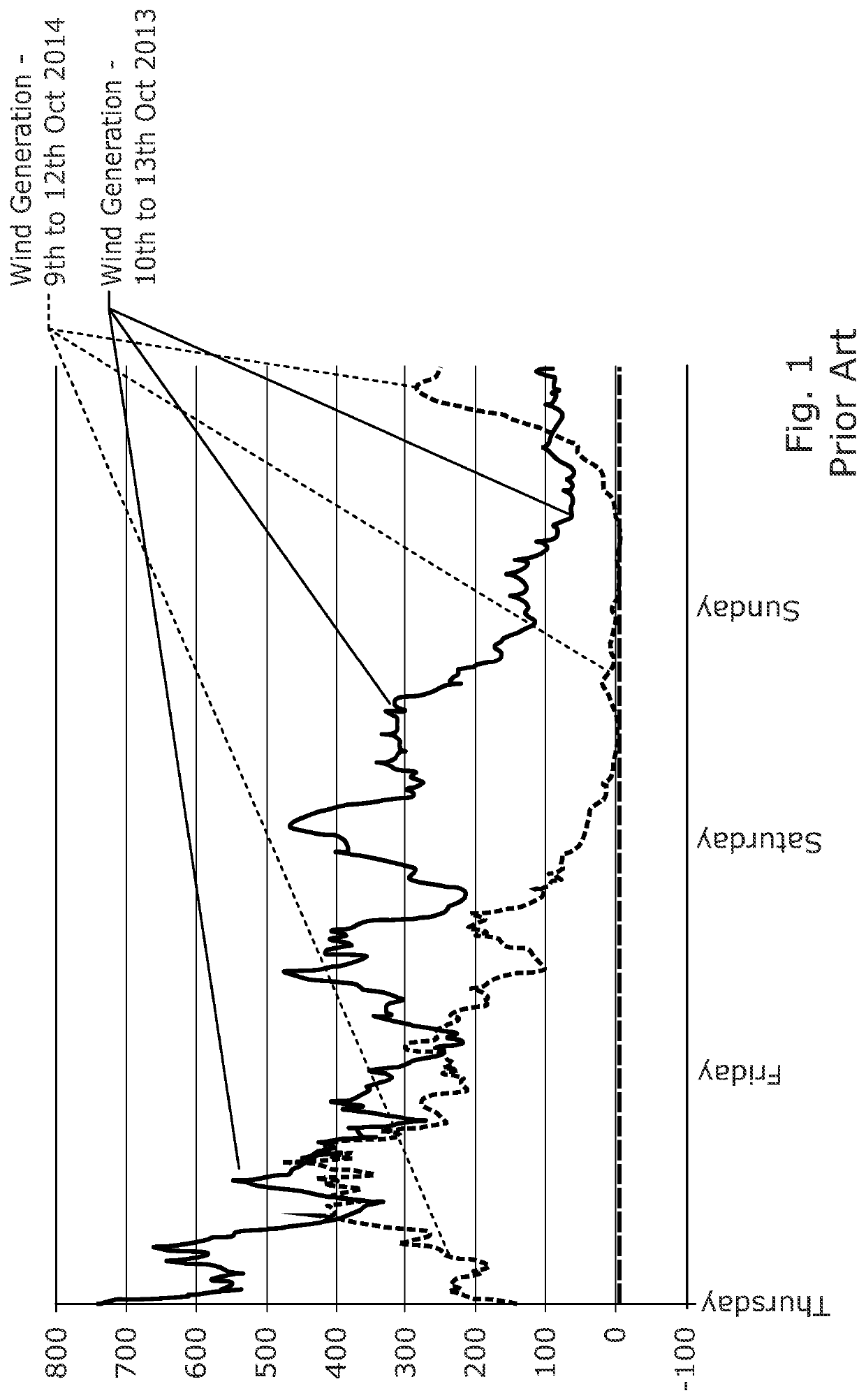
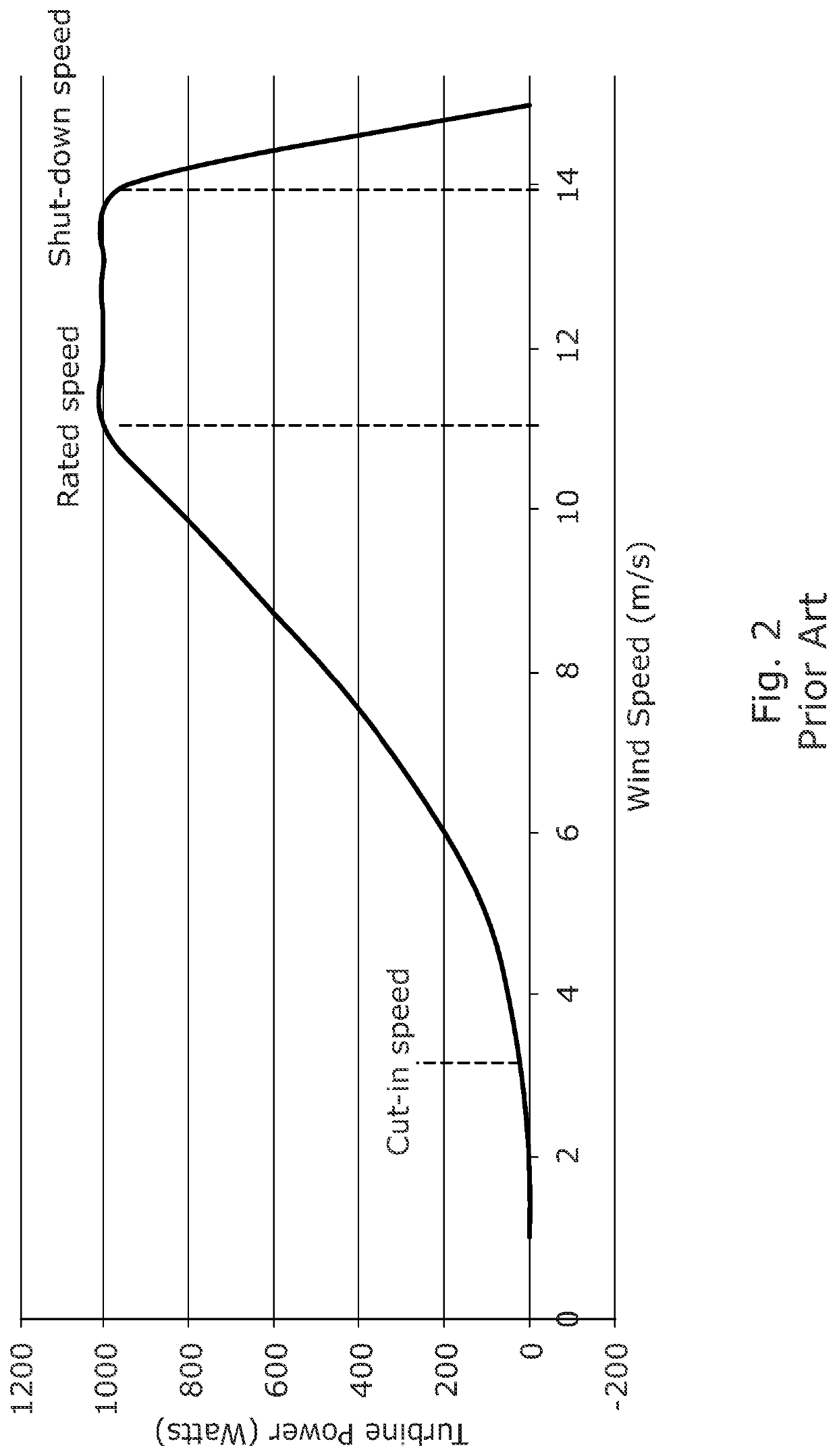
Another problem with wind is that wind speeds can drop below the “cut-in” speed for days at a time, and this can happen at any time.
This is a fatal flaw in any attempt to use wind to deliver dispatchable power.
The current art of wind technology cannot deliver dispatchable power on its own.
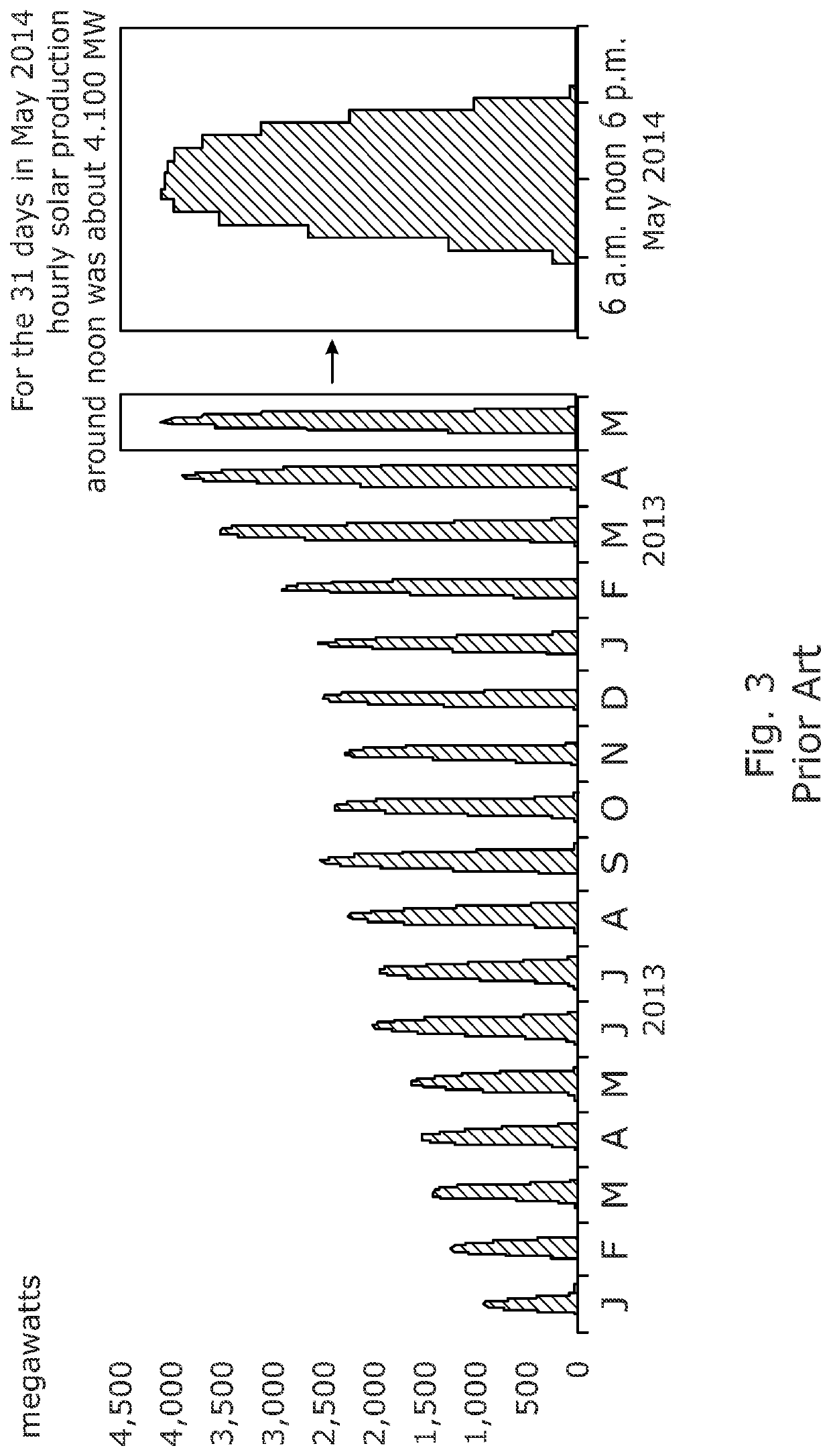
Solar is more predictable than wind, but still has a low capacity factor.
This causes a converse problem; during the summer, a 20 MW solar system will peak at 10 MW instantaneous power.
Furthermore, although it needs less space than wind, solar energy requires approximately one hectare per 1 MW of installed power.
Setting aside commercial considerations, placement of such a large scale solar or wind installation system in environmentally sensitive areas would be undesirable, counter to the cause of preserving the environment, and is likely to be denied a construction license in any case.
Pumped-storage suffers from the double loss from both pumping water up and then generating from it being released through a turbine to generate.
Although it is still in its development phase it does not yet show the potential to offer high capacity factors.
Thus, conventional hydro is not a suitable solution for an EV charging network which can operate “off-grid” as they are not designed to be always on and they require a grid connection.
This can cause unexpected outages of generation and even the permanent cessation of generation.
This phenomenon is extremely difficult to predict.
Finally, geothermal can cause atmospheric emissions of sub-surface chemicals.
However, battery storage is expensive, and installation costs are currently up to US$0.3 million per MWh.
Particularly where a dispatchable supply of electricity is req

Method used


Image

  • Dispatchable renewable power supply
  • Dispatchable renewable power supply
  • Dispatchable renewable power supply

Examples


Example

[0195]In a first embodiment, and with reference to FIG. 4 of the drawings, there is provided an off-grid electric vehicle (EV) charge station (10) capable of providing 100 kW dispatchable power output (PD). The off-grid electric vehicle charge station (10) comprises a base power generator (11) (also referred to as a primary power generator) in the form of a hydroelectric power generator. The hydroelectric power generator is in fluid flow communication with a water source, and comprises a turbine and generator.

[0196]The off-grid electric vehicle charge station (10) further comprises storage capacity in the form of a battery (12) (“grid battery”) electrically coupled to the base power generator (11). A secondary power generator (13) in the form of a solar power generator (comprising photovoltaic cells) is also coupled to the battery (12), and both power generators (11, 13) are configurable to generate power from their respective renewable energy sources and send the power to the batte...

Example

Embodiment 2

[0201]A second exemplary embodiment of the invention comprises the base power generator (11), the battery (12), the control module (14) and the EV charge point (15) as described above.

[0202]Where a reliable energy source is known, it is not necessary to provide a secondary power generator. For example, dams may often have a minimum water flow or spill from the reservoir in order to allow water to flow downstream, reducing the environmental impact of the dam. Therefore, there is a guaranteed water flow at all times of the year. Therefore, the base power generator (11) can be built to specification for the exact amount of water flow, and the battery (12) sized appropriately so as to provide the “off-grid”, always on, EV charging station of the present invention.

[0203]In use, the electric vehicle charge station (10) provides an off-grid, always on power source for EV vehicles and is powered entirely by renewable energy sources. The battery (12) and base power generator (11)...

Example

Embodiment 3

[0204]A third exemplary embodiment comprises commercial premises having a typical power demand during operation hours (8 am-6 pm) of 75 kW, and a maximum power demand of 95 kW. A dispatchable off-grid power supply is provided as per Embodiment 1, capable of providing 100 kW of dispatchable power.


PUM


Abstract

The present invention is concerned with a dispatchable power supply, more particularly an off-grid power supply, more particularly an off-grid electric vehicle charge station, more particularly to an off-grid renewable energy powered electric vehicle charge station.

Description

SCOPE OF THE INVENTION[0001]The present invention is concerned with a dispatchable power supply, for example a dispatchable off-grid power supply, for example an off-grid electric vehicle charge station, for example an off-grid renewable energy powered electric vehicle charge station.[0002]The present invention turns multiple sources of non-dispatchable generation into a dispatchable power source.[0003]Dispatchable power is, by definition, predictable in terms of the instantaneous power it can deliver, and is 100% reliable when loaded with demand, up to 100% of its maximum design power output.BACKGROUND OF THE INVENTION[0004]Electric vehicle (EV) technology is becoming more and more common in many countries around the world as part of a continuing effort to reduce global emissions which are harmful to the environment. Indeed, many countries are introducing policies and statutes relating to harmful emissions, in particular, limiting the sale or even prohibiting the sale of vehicles h...

Claims


Application Information

Patent Timeline
IPC IPC(8): B60L53/57B60L53/52B60L53/51B60L53/63B60L53/53
CPCB60L53/57B60L53/52B60L53/53B60L53/63B60L53/51B60L53/67H02J7/34H02J7/35H02J2300/40H02J2310/48H02J2300/28Y02T90/12Y04S10/126Y02E60/00H02J2300/20
Inventor JANKEL, PAULPOSTLE-FLOYD, HAYDENTAYLOR, DANIEL
Owner AQUANOVIS HLDG
Why Eureka
Try Eureka