Acoustic air data systems

Pending Publication Date: 2020-10-22
ROSEMOUNT AEROSPACE
View PDF0 Cites 1 Cited by
  • Summary
  • Abstract
  • Description
  • Claims
  • Application Information

AI Technical Summary

Benefits of technology

[0008]The transmitter can be configured to face backward along the aircraft for providing at least one of reduced susceptibility to icing, optimized directivity towards the one or more receivers, or extension of the signal just outside

Problems solved by technology

Also, velocity and temperature gradients can attenuate the signal, so existi

Method used


Image

  • Acoustic air data systems

Examples


Example

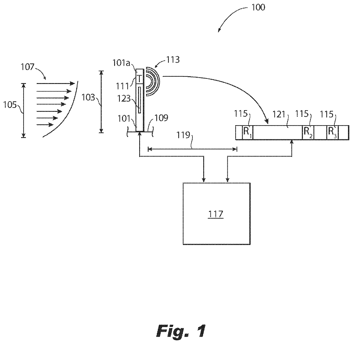
[0019]Reference will now be made to the drawings wherein like reference numerals identify similar structural features or aspects of the subject disclosure. For purposes of explanation and illustration, and not limitation, an illustrative view of an embodiment of a system in accordance with the disclosure is shown in FIG. 1 and is designated generally by reference character 100. Certain embodiments described herein can be used to improve acoustic air data measurements, for example.

[0020]An ultrasonic air data system 100 can include a pole 101 having a length 103 longer than a boundary layer thickness 105 of a boundary layer flow 107 such that at least a distal end 101a of the pole 101 is configured to extend outwardly from an aircraft surface 109 to be at least partially outside of the boundary layer flow 107.

[0021]The system 100 can include a transmitter 111 disposed on or in the pole 101 at or near the distal end 101a of the pole 101 such that the transmitter 111 is located at leas...


PUM


Abstract

An ultrasonic air data system can include a pole having a length longer than a boundary layer thickness of a boundary layer flow such that at least a distal end of the pole is configured to extend outwardly from an aircraft surface to be at least partially outside of the boundary layer flow. The system can include a transmitter disposed on or in the pole at or near the distal end of the pole such that the transmitter is located at least partially outside of the boundary layer flow when in use, wherein the transmitter is configured to output a transmitter signal. The system can include one or more receivers disposed downstream of the pole as defined by the boundary layer flow and configured to receive the transmitter signal.

Description

BACKGROUND1. Field[0001]This disclosure relates to air data system, more specifically to acoustic air data systems (e.g., ultrasonic airspeed, temperature, and / or direction systems).2. Description of Related Art[0002]Aircraft air data systems can utilize ultrasonic sensing for generating airspeed, temperature (e.g., through the speed of sound), and flow direction (e.g., AOA or AOS depending on installation). Performance of an ultrasonic air data system that utilizes an ultrasonic transmitter and an array of receivers and a time-of-flight measurement is directly dependent on a number of factors. The frequency of the sound wave, the distance the sound wave has to travel, the speed of sound of the medium in which it's traveling through, the attenuation of the sound due to a number of factors, and the relative wind speed and direction. Measurement principles such as the sampling rate and the accuracy of any estimation algorithms and calibration are also part of a total performance of th...

Claims


Application Information

Patent Timeline
IPC IPC(8): G01P3/14E05F15/40B64D15/12H04W4/38
CPCE05F15/40B64D15/12H04W4/38G01P3/14B64D43/02G01P5/245G01P13/025G01P1/06
Inventor SLY, JAIMESHANNON, DANIEL W.MATHEIS, BRIAN DANIELELL, TODD ANTHONYKUNIK, WILLIAMKOUSHIK, SUDARSHAN N.
Owner ROSEMOUNT AEROSPACE
Why Eureka
Try Eureka