
Resin molded product and molding method and molding apparatus thereof

a technology of resin molded products and molding methods, which is applied in the direction of foundation moulding apparatus, lighting and heating apparatus, instruments, etc., can solve the problems of degradation of the appearance of light guides or lamps, high cost, and difficulty in reliably preventing the generation of weld lines in the molded portions, so as to simplify the configuration of the resin stopper or the mold, good appearance, and uniform brightness

Inactive Publication Date: 2014-05-29
KOITO MFG CO LTD
View PDF0 Cites 2 Cited by
  • Summary
  • Abstract
  • Description
  • Claims
  • Application Information

AI Technical Summary

Benefits of technology

The present invention provides a resin molded product that has good appearance and uniform brightness without the occurrence of weld lines. The invention solves the problem of deterioration in the molding quality by preventing resin flow disturbance and resin filling property degradation. Moreover, the invention simplifies the molding process and reduces the manufacturing costs by eliminating the need for a movable piece. The technical effects of the invention allow for the manufacturing of a resin molded product with high quality and good appearance.

Problems solved by technology

Thus, the emitted light becomes glare light that interferes with marker lamp light distribution, or degradation of the appearance of the light guide or the lamp occurs.
However, in order to perform the adjustment of such resin injection amount, for example, it may be necessary to make the opening sizes of the gates different from each other, and the structure of the mold becomes complicated, resulting in high costs.
Additionally, it is difficult to reliably prevent generation of the weld line in the molded portions.
When the convex portion is disposed in a portion of the cavity in order to apply the technique of Patent Document 1 to the resin molding of the light guide, the flow of resin is always delayed in the convex portion and disturbance occurs in the flow of the resin.
Therefore, deterioration of the resin filling property, such as generation of voids (bubbles) in the portion, occurs, may result in decrease of molding quality.
However, a mechanism for moving the movable piece is required, and the structure of a molding apparatus becomes complicated, resulting in high costs of the mold.
Also, it is difficult to take the timing at which the movable piece is moved, so molding work becomes complicated.

Method used


Image

  • Resin molded product and molding method and molding apparatus thereof
  • Resin molded product and molding method and molding apparatus thereof
  • Resin molded product and molding method and molding apparatus thereof

Examples


Embodiment Construction

[0020]Embodiments of the present invention will be described with reference to the drawings. In embodiments of the invention, numerous specific details are set forth in order to provide a more thorough understanding of the invention. However, it will be apparent to one of ordinary skill in the art that the invention may be practiced without these specific details. In other instances, well-known features have not been described in detail to avoid obscuring the invention.

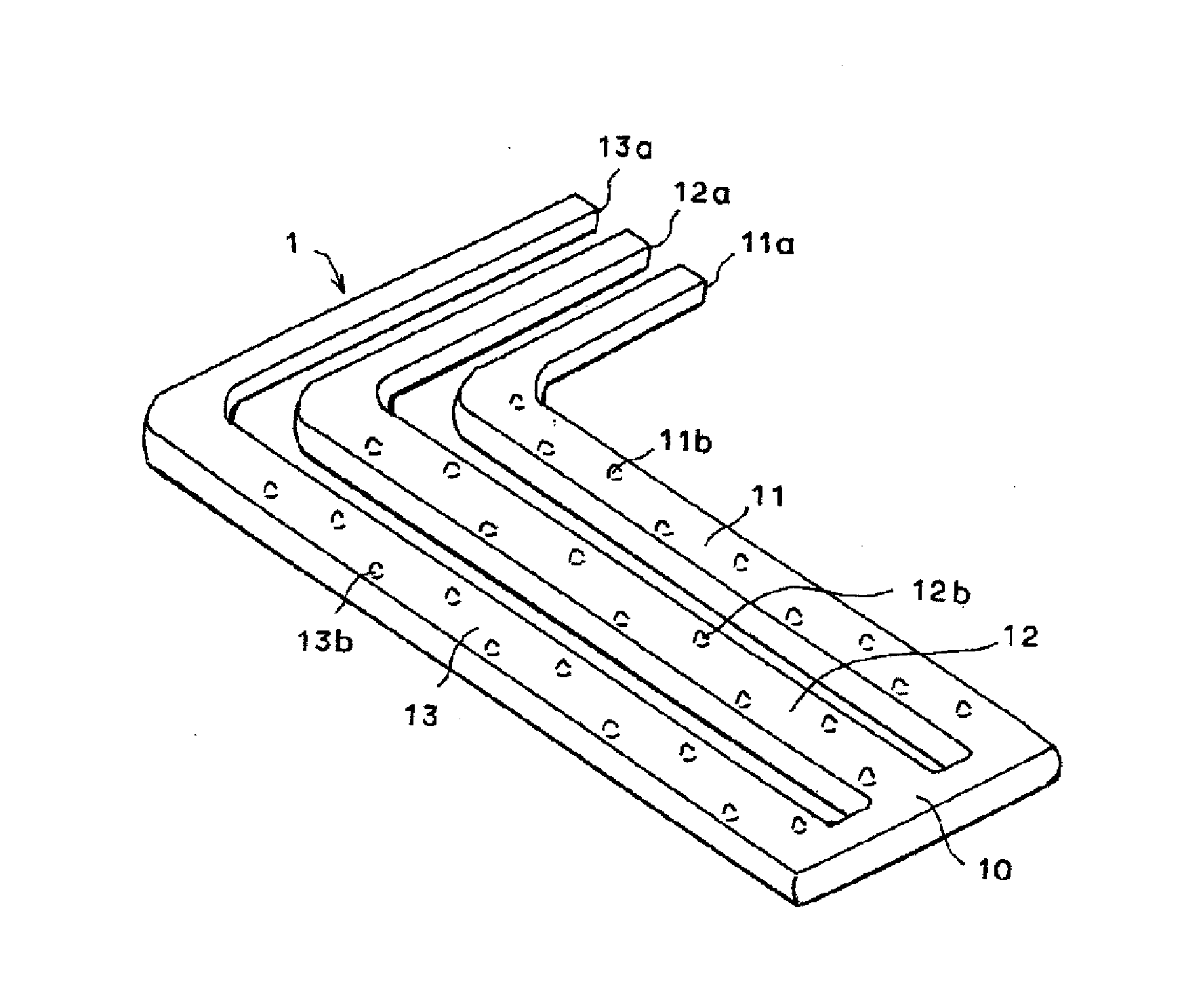
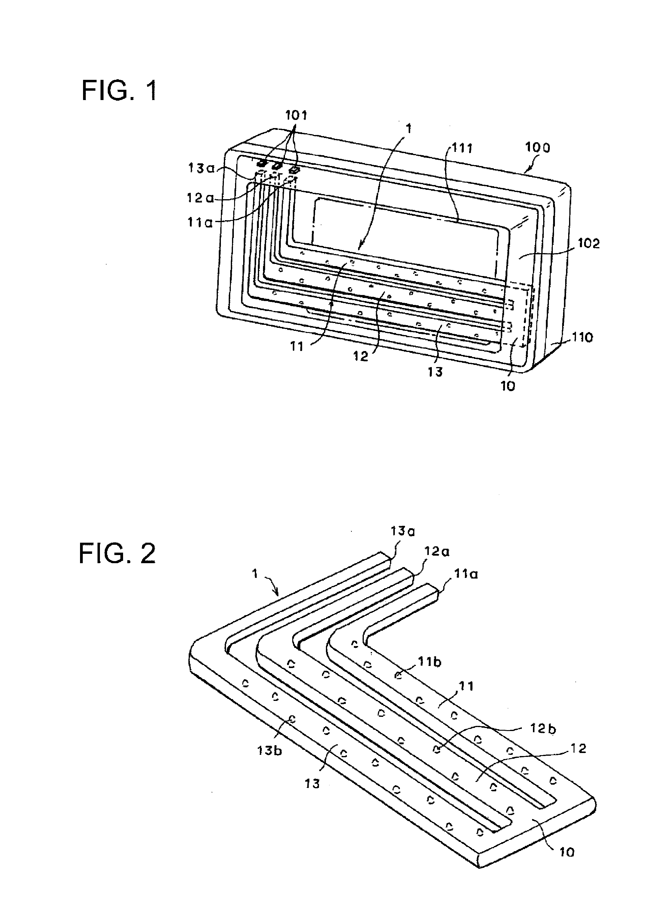
[0021]In this embodiment, an example will be described, in which a resin molded product according to one or more embodiments of the present invention is configured as a curved comb-like light guide 1 in which respective distal end portions of a plurality of molded portions are connected to each other by a connecting portion as shown in FIG. 1. That is, the light guide 1, as shown in FIG. 2, has three generally L-shaped molded portions 11, 12, and 13 that are each formed such that a base end-side region is narrow and a...


PUM

PropertyMeasurementUnit
translucentaaaaaaaaaa
pressureaaaaaaaaaa
lengthaaaaaaaaaa

Abstract

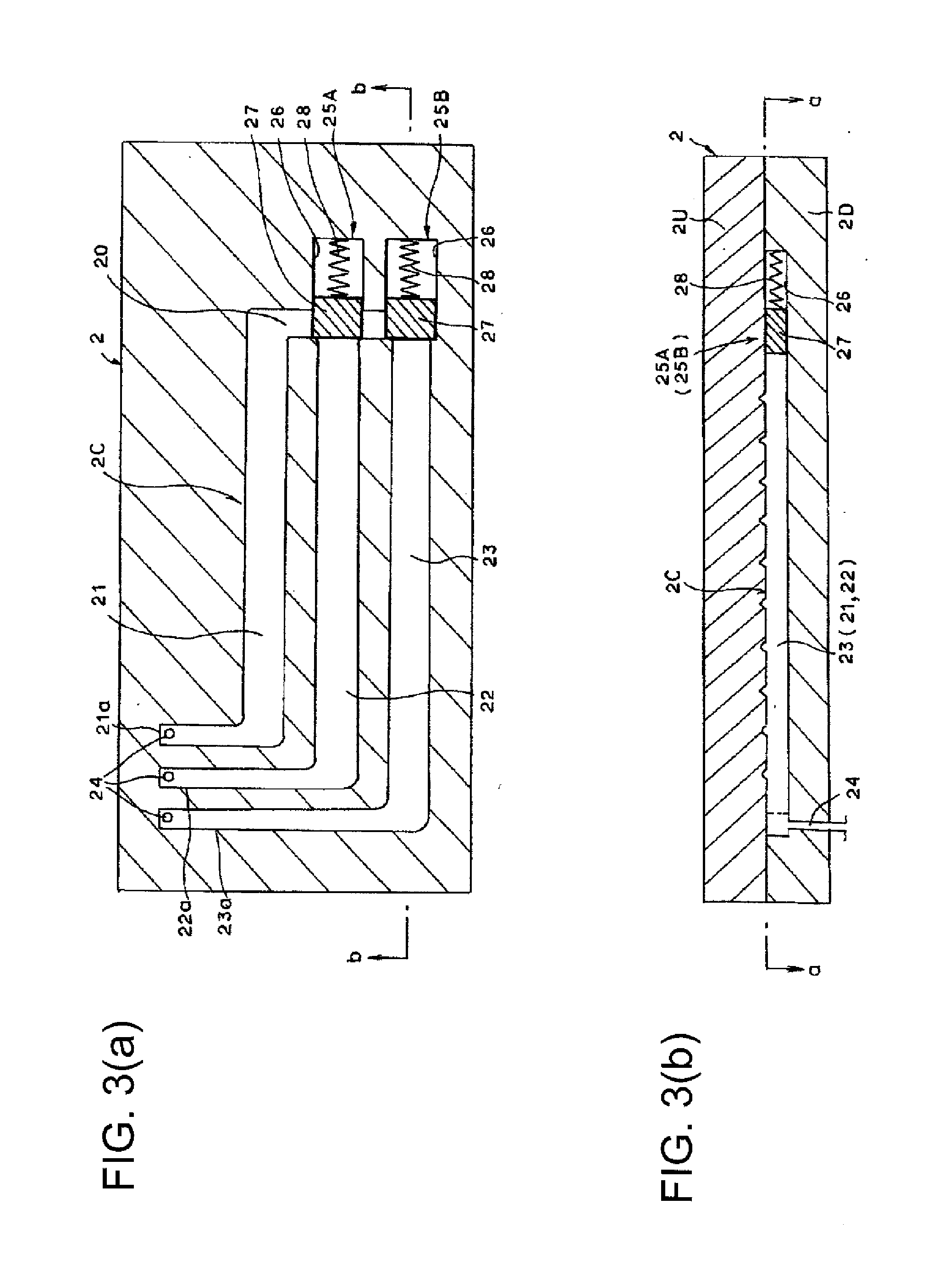
A method for molding a resin molded product, including at least first and second molded portions having respective distal ends thereof connected to each other by a connecting portion, has a pouring step of pouring the resin into base end sides of the first and second molded portions, a stopping step of stopping the resin that has flowed through the first molded portion and the connecting portion and is about to flow in the second molded portion, and a releasing step of releasing the stoppage of the resin after the second molded portion is filled with the resin.

Description

BACKGROUNDTechnical Field[0001]The present invention relates to a resin molded product molded by an injection molding method using a mold, and particularly, to a resin molded product including a plurality of linear portions connected to each other at portions thereof, and a molding method and a molding apparatus thereof.Related Art[0002]In lamps for a vehicle in recent years, in order to enhance the designing effect in the appearance of the lamps in addition to the indicator function of the related art, a designed light guide is arranged within the lamps. A light guide with a design in which a plurality of linear light guides are connected to each other at end portions thereof is suggested as one of such types of light guides. For example, in a lamp 100 shown in FIG. 1, a grid-like or comb-like light guide 1, in which a plurality of (here, three) generally L-shaped molded portions 11, 12, and 13 are connected to each other at a connecting portion 10, is disposed together with a ligh...

Claims


Application Information

Patent Timeline
Patent Type & Authority Applications(United States)
IPC IPC(8): G02B6/255B29D11/00F21W107/10
CPCB29C45/0025B29C45/0046B29D11/00663B29C2045/0089B29C2045/0049B29L2011/0075F21S43/14F21S43/239F21S43/245F21S43/249Y10T428/192G02B6/2551
Inventor OMOTE, MASASHI
Owner KOITO MFG CO LTD
Learn More