MEMS debrider drive train

a drive train and micro-scale technology, applied in the field of micro- and millimeter-scale tissue debridement devices, can solve the problems of clogging the tissue removal lumen, affecting the treatment effect, so as to reduce backlash and reduce backlash

Inactive Publication Date: 2014-05-29
MICROFAB
View PDF3 Cites 10 Cited by
  • Summary
  • Abstract
  • Description
  • Claims
  • Application Information

AI Technical Summary

Benefits of technology

The patent text discusses a design feature where the tips of the teeth of spur gears are bulged to reduce backlash between the gears. This design feature improves the performance of the gear system and increases efficiency.

Problems solved by technology

Some debrider devices with relatively large dimensions risk removing unintended tissue from the subject, or damaging the unintended tissue.
Since the tissue pieces being removed commonly have dimensions that are 1 to 2 lumen diameters in length, the tissue pieces can often clog the tissue removal lumen.

Method used


Image

  • MEMS debrider drive train
  • MEMS debrider drive train
  • MEMS debrider drive train

Examples


Embodiment Construction

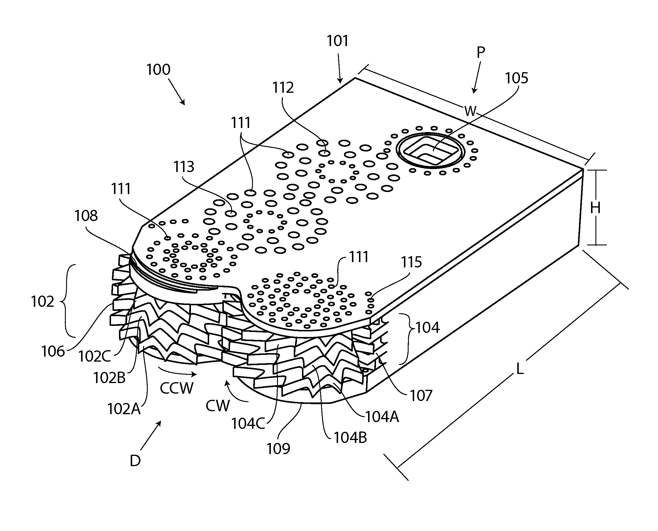
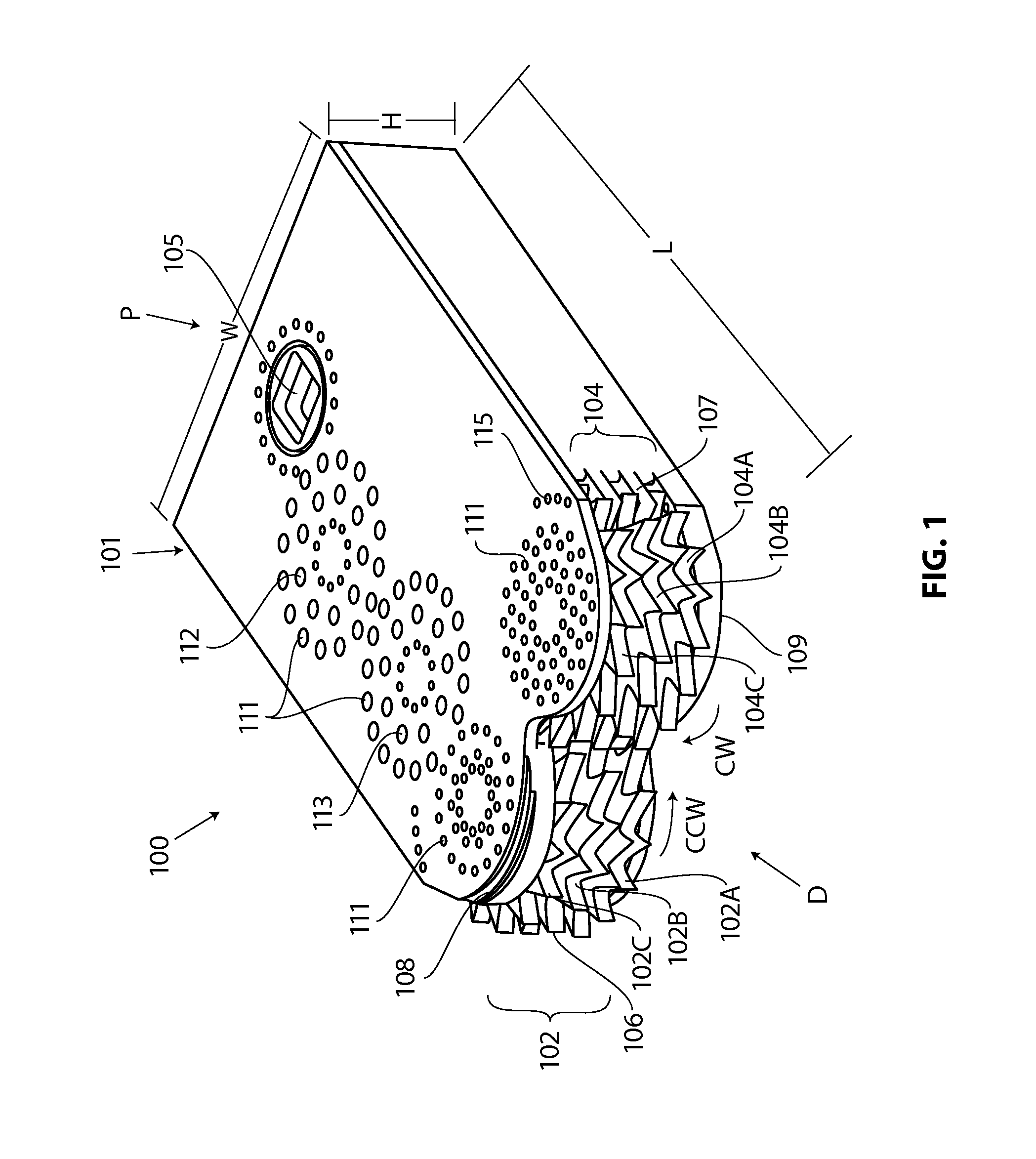
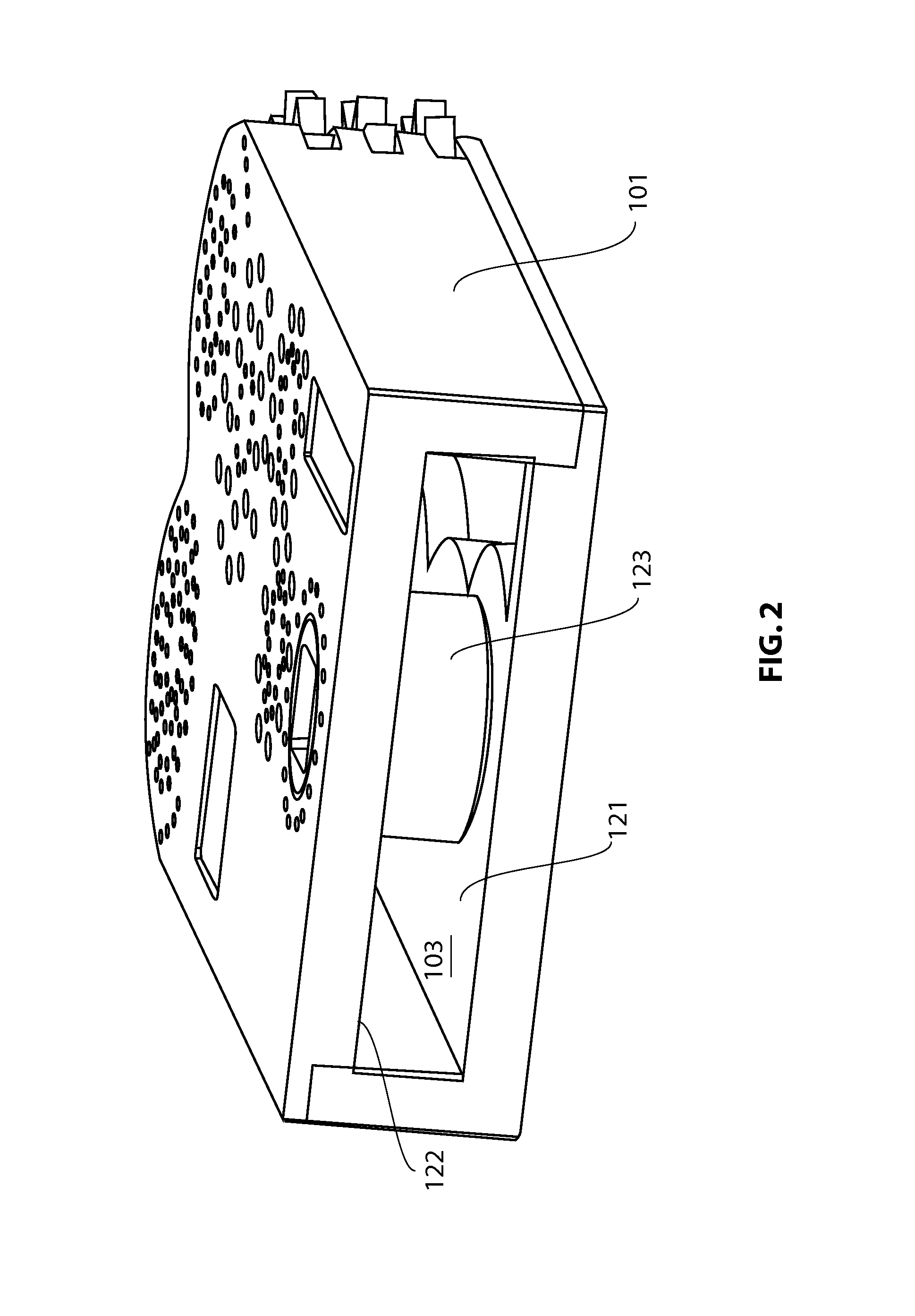
[0058]FIGS. 1-3 illustrate an exemplary embodiment of a working end of a tissue removal device, which can be fabricated wholly or in part by electrochemical fabrication techniques, such as those described or referenced herein. Tissue removal device working end 100 has a distal region “D” and proximal region “P,” and includes housing 101 and blade stacks 102 and 104. Blade stacks 102 and 104 include a plurality of blades 102A-102C and 104A-104C, respectively. Three blades are shown in each stack, although the blade stacks can have one or more blades. Each of the blades includes a plurality of teeth 106 (see FIG. 3), some of which are shown projecting from housing 101 and configured to engage and process tissue. Processing tissue as used herein includes any of cutting tissue, shredding tissue, capturing tissue, any other manipulation of tissue as described herein, or any combination thereof. The working end of the device generally has a length L, height H, and width W. Housing 101 can...


PUM


Abstract

A medical device such as for removing tissue from a subject is provided with a distal housing configured with a tissue cutter assembly, an elongate member coupled to the distal housing and having an outer tube and an inner drive tube with a crown gear located on a distal end thereof, first and second rotatable members each rotatably mounted to the tissue cutter assembly, a first drive gear train coupled between the crown gear and the first rotatable member, and a second drive gear train coupled between the crown gear and the second rotatable member. The first and second drive gear trains are configured to drive the first and second rotatable members, respectively, in opposite directions. Concave and convex gear tooth profiles are also disclosed for improved performance of the first and second drive gear trains.

Description

CROSS REFERENCE TO RELATED APPLICATIONS[0001]This application claims priority to U.S. Provisional Application No. 61 / 731,440 filed on Nov. 29, 2012.[0002]This application is related to the following U.S. applications: application Ser. No. 13 / 007,578 filed Jan. 14, 2011; application Ser. No. 12 / 490,295 filed Jun. 23, 2009; Provisional Application No. 61 / 075,006 filed Jun. 23, 2008; Provisional Application No. 61 / 164,864 filed Mar. 30, 2009; Provisional Application No. 61 / 164,883 filed Mar. 30, 2009; application Ser. No. 12 / 490,301 filed Jun. 23, 2009; Provisional Application No. 61 / 075,006 filed Jun. 23, 2008; Provisional Application No. 61 / 164,883 filed Mar. 30, 2009; Provisional Application No. 61 / 408,558 filed Oct. 29, 2010; Provisional Application No. 61 / 710,608 filed Oct. 5, 2012; application Ser. No. 13 / 289,994 filed Nov. 11, 2011; application Ser. No. 13 / 659,734 filed Oct. 24, 2012; application Ser. No. 13 / 388,653 filed Apr. 16, 2012; application Ser. No. 12 / 491,220 filed on J...

Claims


Application Information

Patent Timeline
IPC IPC(8): A61B17/32
CPCA61B17/32002A61B17/1671A61B2017/320024A61B2017/320032A61B2017/32006A61B2217/007
Inventor SCHMITZ, GREGORY P.LEGUIDLEGUID, RONALDWU, MING-TINGPEREA, JUAN DIEGOARCENIO, GREGORY B.
Owner MICROFAB
Why Eureka
Try Eureka