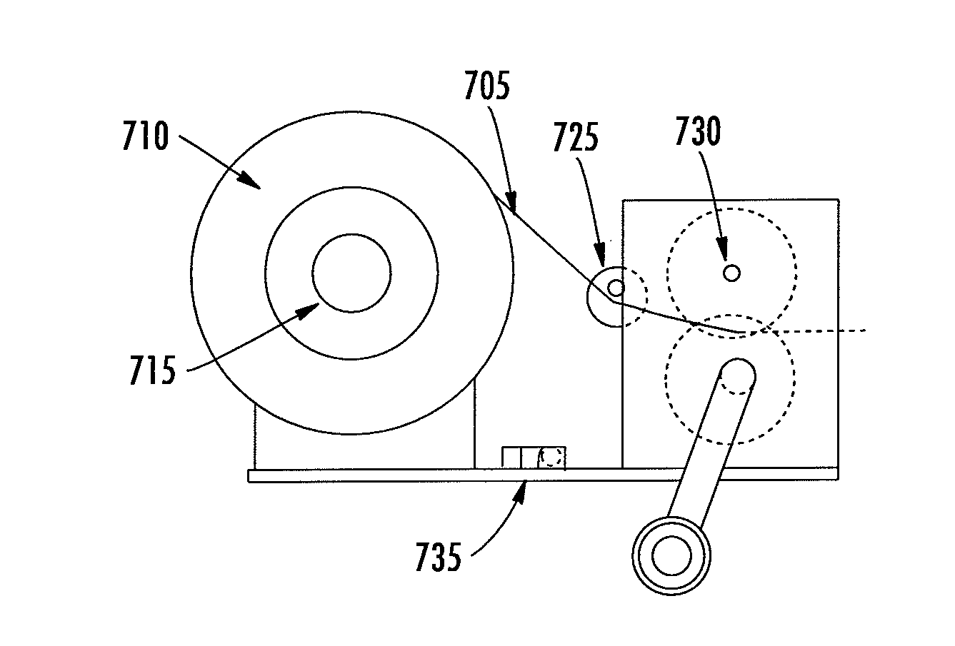
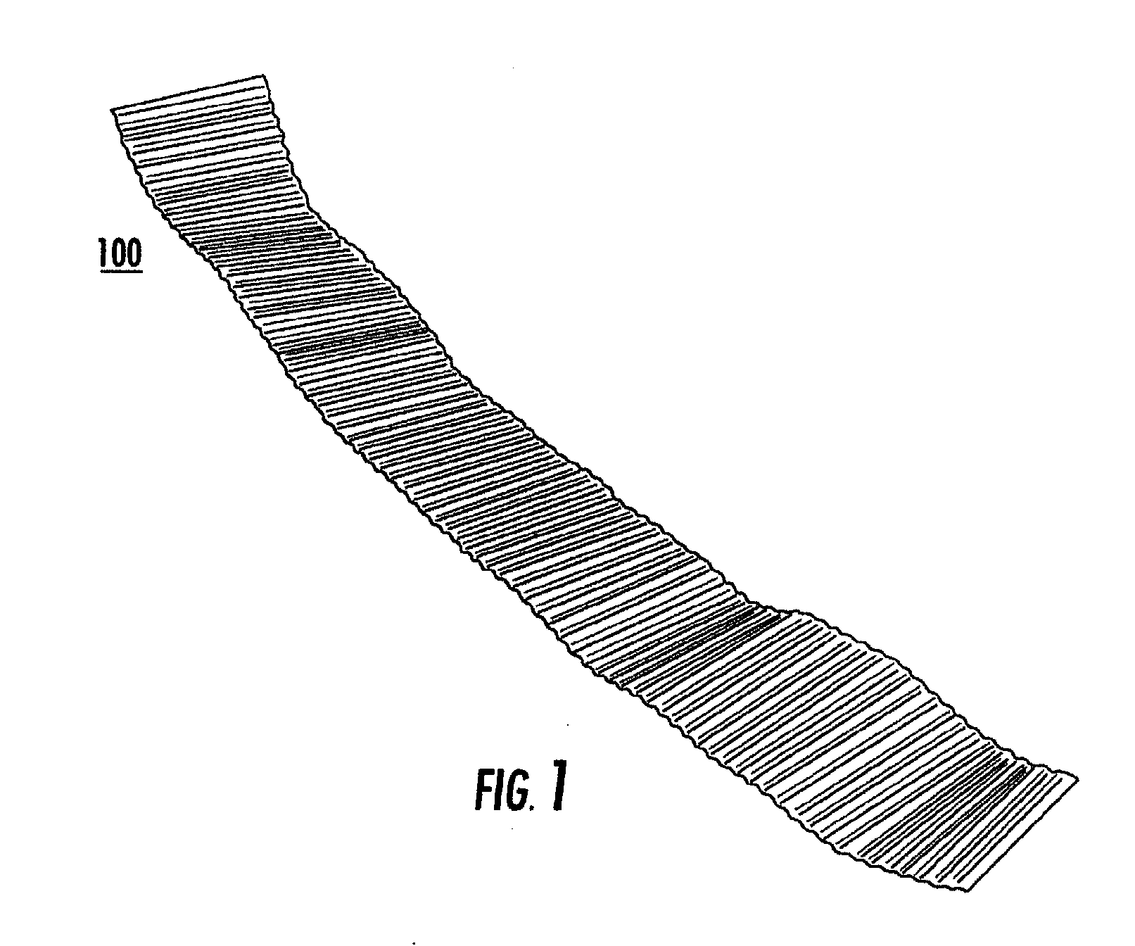
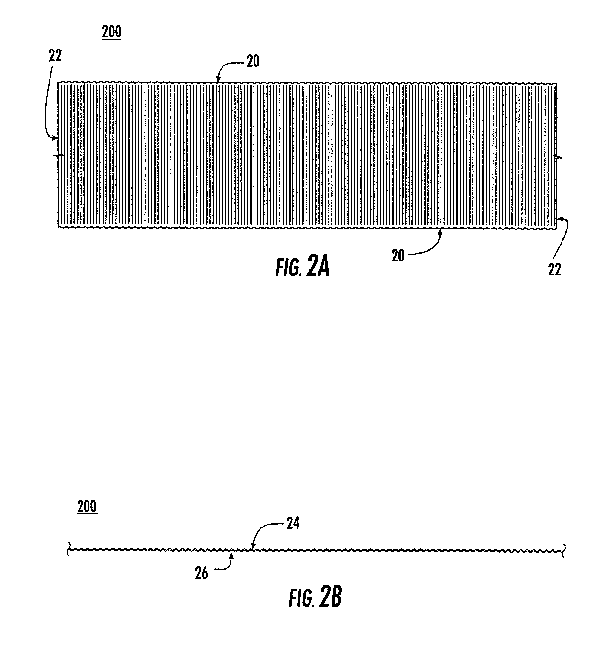
Corrugated metallic foil tape and device for making corrugated metallic foil tape

a technology of corrugated metallic foil and corrugated tape, which is applied in the direction of press ram, manufacturing tools, shaping tools, etc., can solve the problems of cumbersome and messy application, low production efficiency, and inability to easily remove or adjust, so as to achieve efficient, clean and resilient

Active Publication Date: 2014-06-05
SHURTAPE TECH LLC
View PDF9 Cites 1 Cited by
  • Summary
  • Abstract
  • Description
  • Claims
  • Application Information

AI Technical Summary

Benefits of technology

[0011]The corrugated metallic foil tape of the present invention solves the problems associated with energy loss in HVAC

Problems solved by technology

One such example is with loss of energy in residential or commercial buildings.
Among the disadvantages with such sealants and mastics, for example, are that they are often cumbersome and messy to apply and, once applied, are typically not readily removable or adjustable.
There are also known disadvantages associated with duct tape.
. . duct tape is not permitted as a sealant on any metal ducts.” For example, over time conventional duct tape cracks and results in leaks in the system.
This creates problems as the joints or seams in a HVAC u

Method used


Image

  • Corrugated metallic foil tape and device for making corrugated metallic foil tape
  • Corrugated metallic foil tape and device for making corrugated metallic foil tape
  • Corrugated metallic foil tape and device for making corrugated metallic foil tape

Examples


example

Duct Tape

[0063]An experiment was conducted for the following tapes in accordance with ASTM E2342 and the results of the experiment are set forth in Table 1.

TABLE 1Time to Failure in Days Tape (Tested to the requirements of(Minimum 60 days ASTM E2342)required by the test)Duct Tape [Covalence Nashua 557,1-13Covalence Nashua 558 CA, Shurtape PC857, and Shurtape PC 858 CA]Duct tape backing with acrylic adhesive1-35Corrugated foil tape with acrylic adhesive69+in accordance with the present invention(using Shurtape AF 100 aluminum foil tapeprior to corrugation)


PUM

PropertyMeasurementUnit
Diameteraaaaaaaaaa
Lengthaaaaaaaaaa
Lengthaaaaaaaaaa

Abstract

A corrugator system for corrugating metallic foil tape. The corrugated metallic foil tape made by the system is suitable to be applied to contoured or three-dimensional surfaces, and is particularly suitable for use in sealing or joining components of heat, ventilation, and air conditioning (HVAC) units.

Description

CROSS-REFERENCE TO RELATED APPLICATIONS[0001]This application is a continuation-in-part of and thus is entitled to the benefit of, and claims priority from U.S. Divisional patent application Ser. No. 13 / 796,456, filed on Mar. 12, 2013, which claims the benefit of U.S. Divisional patent application Ser. No. 13 / 406,575, filed on Feb. 28, 2012, which claims the benefit of U.S. patent application Ser. No. 12 / 290,842, filed on Nov. 4, 2008. The disclosures of which are incorporated herein by reference in their entireties.FIELD OF THE INVENTION[0002]The present invention relates to a corrugated metallic foil tape for use in heating, ventilation, and air conditioning units, or related applications and a device for making a corrugated metallic foil tape.BACKGROUND OF THE INVENTION[0003]It is of growing global concern not only to conserve energy but also to mitigate loss of energy. One such example is with loss of energy in residential or commercial buildings.[0004]There are many known appro...

Claims


Application Information

Patent Timeline
IPC IPC(8): B31F1/20C09J7/28
CPCB31F1/20C09J2421/00C09J2431/00C09J2433/00C09J2475/00C09J2483/00C09J7/28B65H2301/5122B31F1/26
Inventor FIDAN, MUZAFFERSTAMATOUKOS, GEORGE
Owner SHURTAPE TECH LLC
Why Eureka
Try Eureka