

Check valve
- Summary
- Abstract
- Description
- Claims
- Application Information
AI Technical Summary
Benefits of technology
Problems solved by technology
Method used
Image

Examples
Embodiment Construction
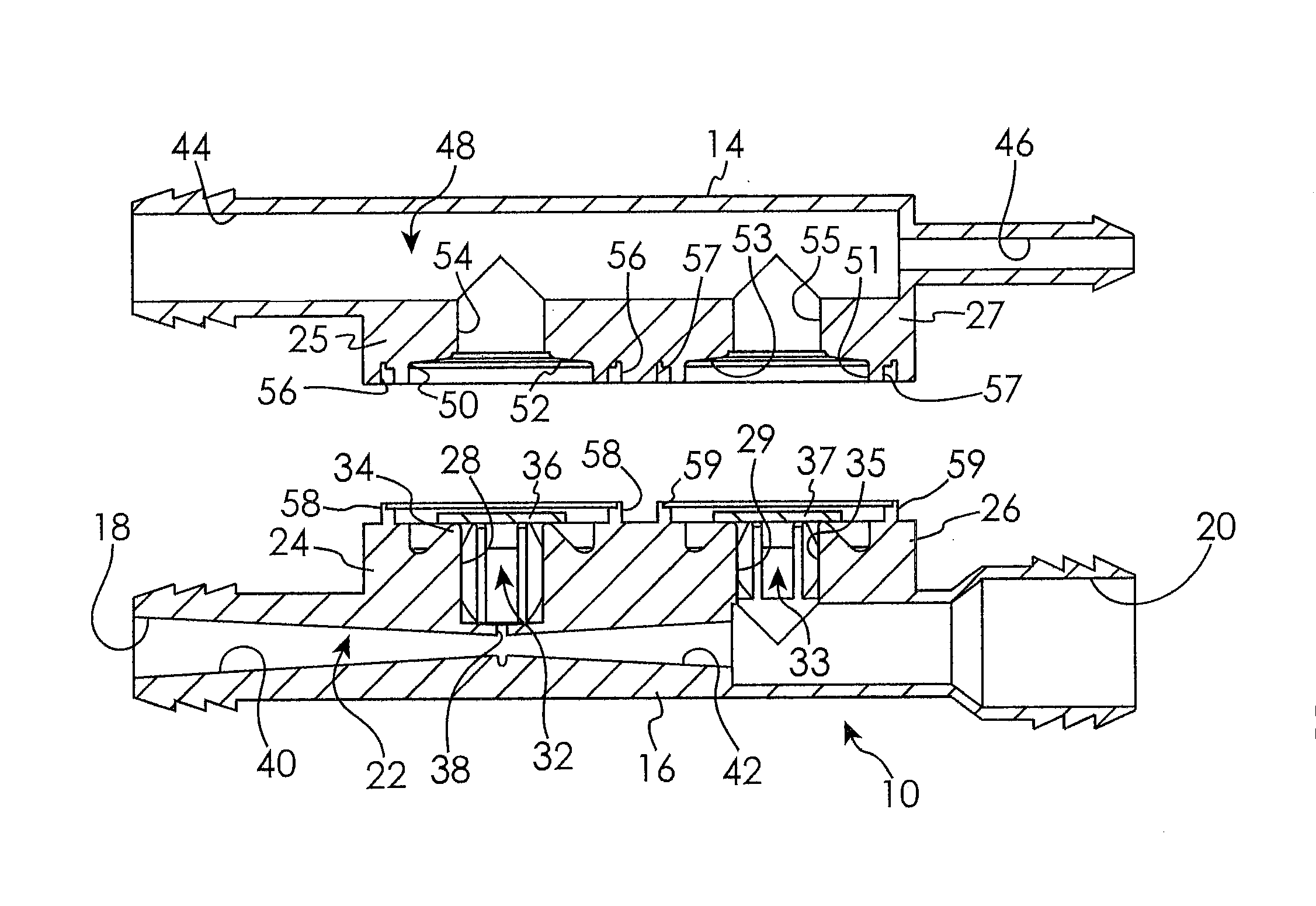
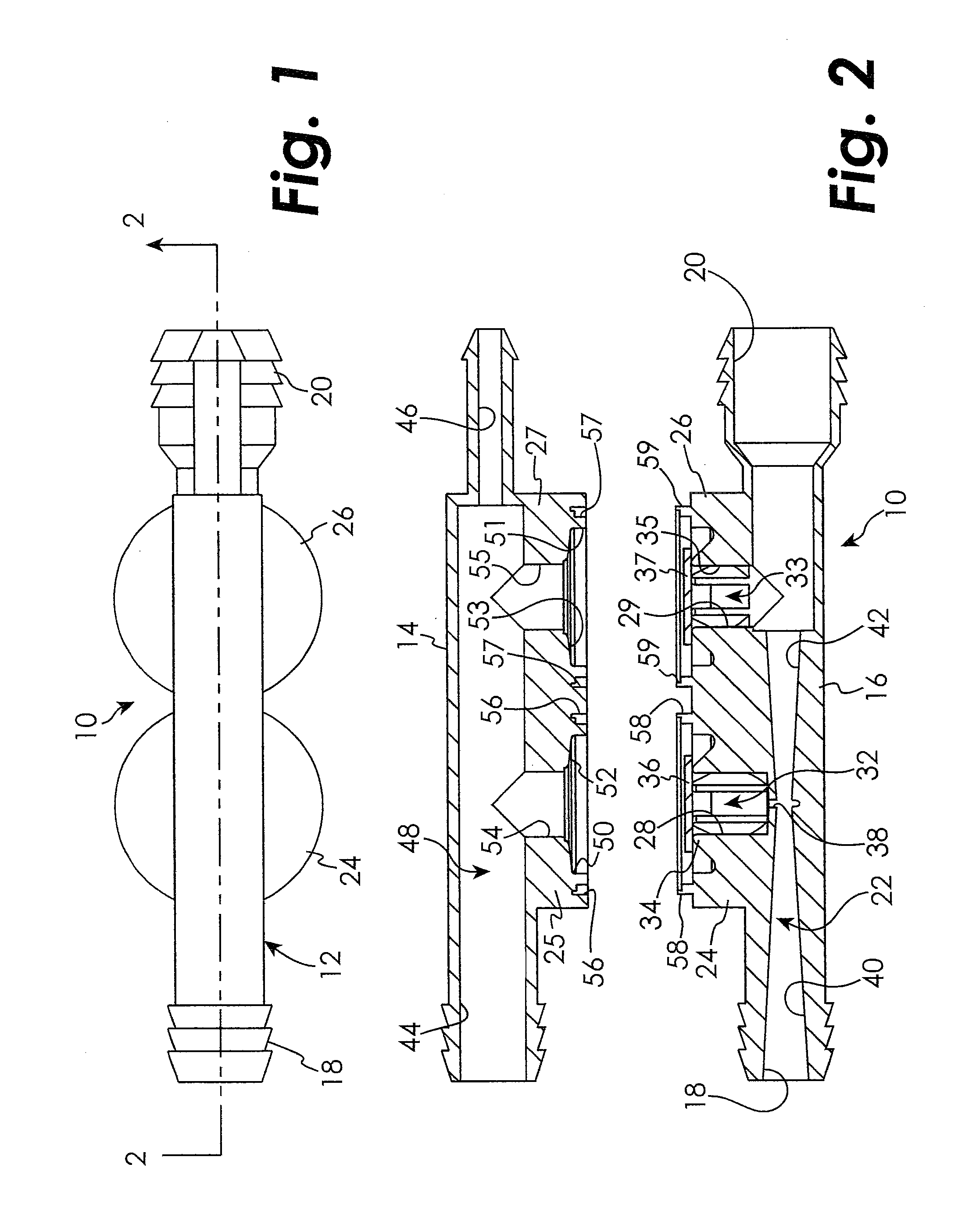
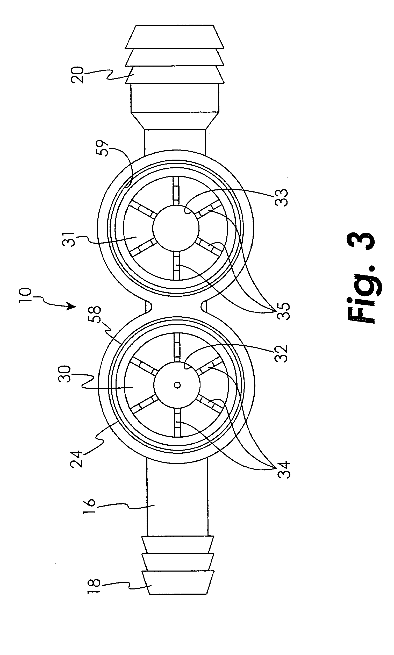
[0002]This present disclosure relates to valves, and will have application to check valves used in internal combustion engines.
BACKGROUND OF THE DISCLOSED EMBODIMENTS
[0003]Internal combustion engines have long employed air flow conduits to provide vacuum assist for automobile subsystems, such as brakes, automatic transmissions and others. These systems often employed check valves located along the air flow conduit to prevent subsystem back pressure from reaching the engine. A typical check valve of this sort is described in U.S. Pat. No. 3,889,710.
[0004]Prior check valves employed either a continuous diameter airway or employed multiple valves and hoses to create a venturi effect and act as a vacuum booster for the subsystem to which it was associated. Space limitations in the automobile engine compartment all but preclude the use of multiple valve-hose systems, while the prior art continuous diameter airways did not provide the increased power boost desired to implement the brakes ...
PUM
 Abstract
Description
Claims
Application Information