Check valve

a check valve and valve body technology, applied in the field of valves, can solve the problems of not providing the increased power boost desired for the implementation of brakes or other subsystems, and achieve the effect of enhancing air flow and maximising vacuum boos

Inactive Publication Date: 2011-08-04
TECHNIPLAS US LLC
View PDF22 Cites 123 Cited by
  • Summary
  • Abstract
  • Description
  • Claims
  • Application Information

AI Technical Summary

Benefits of technology

[0006]In one embodiment, a check valve is disclosed, comprising: a valve body having a first air inlet port, an air outlet port in air flow communication with said first air inlet port to define a first air passageway, a second air inlet port in air flow communication with said first air inlet port and said air outlet port wherein air is drawn from said second air inlet port towards said air outlet port; a valve positioned between said first air passageway and said second air inlet port for inhibiting air flow from said first air passageway through said second air inlet port, said valve comprising: a valve seat positioned between said first and second inlet ports having an opening communicating with said first air passageway; and a flexible seal diaphragm positioned in said valve seat for responding to air exiting said second air inlet port under outside vacuum influence and for seating against said valve seat to prevent air flow from said first air passageway from exiting through said second air inlet port; wherein said flexible seal diaphragm has a non-constant radius; and a venturi conduit positioned between said first air inlet port and said outlet port, said venturi conduit enhancing air flow through said outlet port with a corresponding enhancement of air drawn from said second air inlet port towards said outlet port; wherein said venturi conduit is positioned immediately adjacent said valve seat opening to provide maximum vacuum boost through the valve seat.

Problems solved by technology

Space limitations in the automobile engine compartment all but preclude the use of multiple valve-hose systems, while the prior art continuous diameter airways did not provide the increased power boost desired to implement the brakes or other subsystems.

Method used


Image

  • Check valve
  • Check valve
  • Check valve

Examples


Embodiment Construction

[0017]For the purposes of promoting an understanding of the principles of the invention, reference will now be made to certain embodiments and specific language will be used to describe the same. It will nevertheless be understood that no limitation of the scope of the invention is thereby intended, and alterations and modifications in the illustrated device, and further applications of the principles of the invention as illustrated therein are herein contemplated as would normally occur to one skilled in the art to which the invention relates.

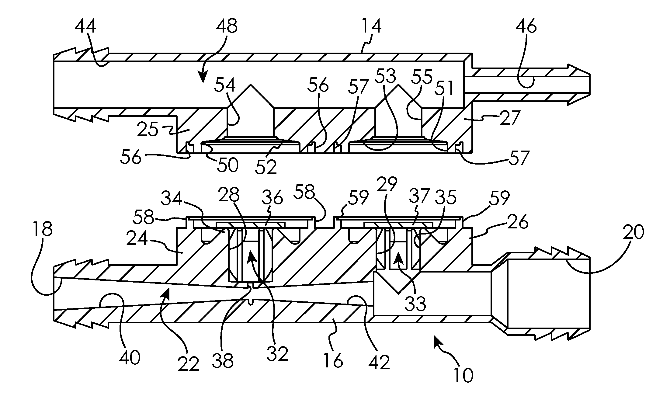
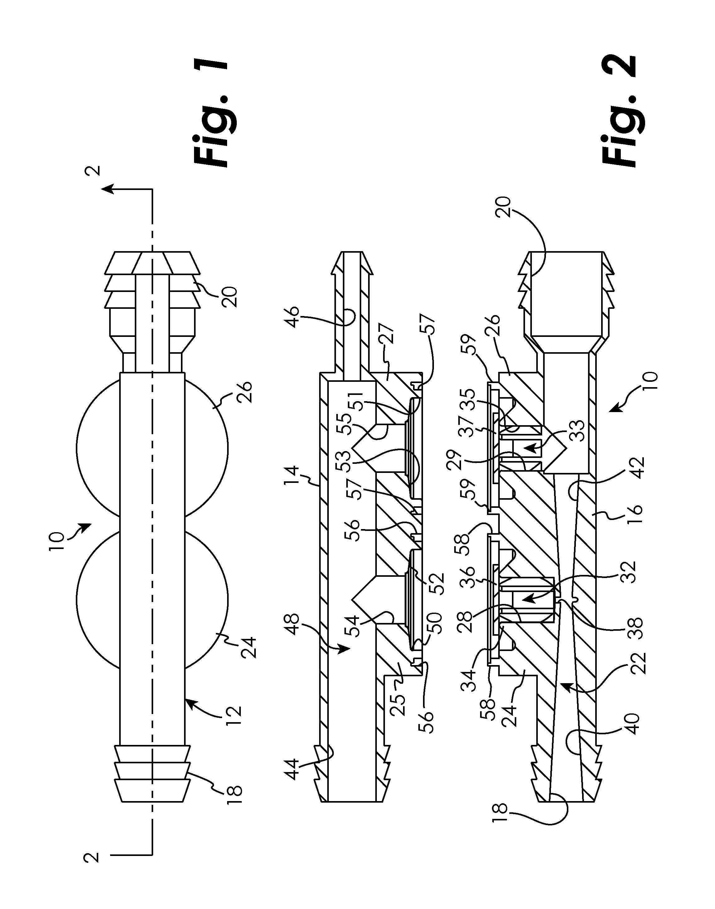
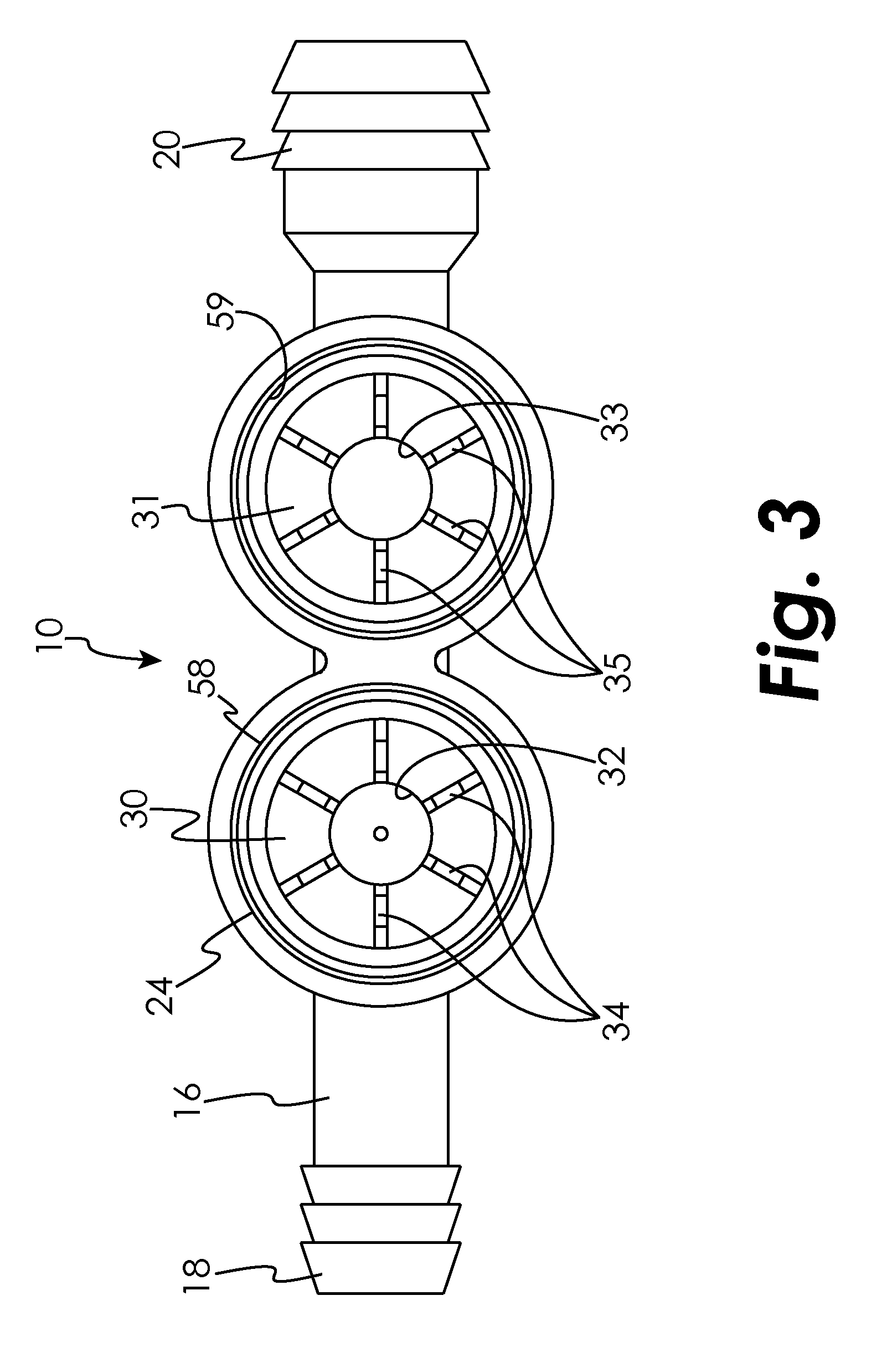
[0018]Referring now to the drawings, a check valve is illustrated and generally referred to as 10. Check valve 10 is normally employed in an internal combustion engine in the air flow line between the engine block and the air intake port at the full mixing port, normally a carburetor or fuel injection port. For clarity, the engine, carburetor, hose connections, and subsystems are not shown, and it is understood that these ports are common to t...


PUM


Abstract

A check valve which is positioned in the vacuum air line of an internal combustion engine. The check valve includes a single-piece valve body having an outlet port and two or more inlet ports, with one outlet port located substantially in line with the inlet port and connected by a venturi tube. The second inlet port is separated from the main air flow line by the valve stem and a diaphragm which allows communication there between and prevents back pressure. The second inlet port communicates with the outlet port through the valve stem and a second venturi tube which provides a vacuum boost to a device, usually vehicle brakes, connected to the inlet. The use of seal diaphragms having a non-constant radius allows for faster recovery time for replenishment than prior art devices.

Description

FIELD OF THE DISCLOSURE[0001]This present disclosure relates to valves, and will have application to check valves used in internal combustion engines.BACKGROUND OF THE DISCLOSURE[0002]Internal combustion engines have long employed air flow conduits to provide vacuum assist for automobile subsystems, such as brakes, automatic transmissions and others. These systems often employed check valves located along the air flow conduit to prevent subsystem back pressure from reaching the engine. A typical check valve of this sort is described in U.S. Pat. No. 3,889,710.[0003]Prior check valves employed either a continuous diameter airway or employed multiple valves and hoses to create a venturi effect and act as a vacuum booster for the subsystem to which it was associated. Space limitations in the automobile engine compartment all but preclude the use of multiple valve-hose systems, while the prior art continuous diameter airways did not provide the increased power boost desired to implement...

Claims


Application Information

Patent Timeline
Patent Type & Authority Applications(United States)
IPC IPC(8): F16K15/00
CPCB60T17/02F16K15/141B60T17/04Y10T137/7897
Inventor SPARAZYNSKI, BERNARD JOSEPH
Owner TECHNIPLAS US LLC
Why Eureka
Try Eureka