Particle beam system and pattern data generation method for particle beam system

a particle beam and pattern data technology, applied in the field of particle beam systems, can solve the problems of reducing the number of steps needed, requiring an extremely large number of steps, and a very large amount of time, and achieve the effect of reducing the number of steps

Active Publication Date: 2014-06-05
HITACHI LTD
View PDF7 Cites 12 Cited by
  • Summary
  • Abstract
  • Description
  • Claims
  • Application Information

AI Technical Summary

Benefits of technology

[0012]In the present invention, new control pattern data can be automatically generated by the division/reuse of existing adjusted control pattern data, and to obtain multi-energy extraction pattern data, energy change control pattern data can be automatically generated by use o

Problems solved by technology

As a result, the generation of control pattern data has traditionally required an extremely large number of steps and a very great de

Method used


Image

  • Particle beam system and pattern data generation method for particle beam system
  • Particle beam system and pattern data generation method for particle beam system
  • Particle beam system and pattern data generation method for particle beam system

Examples


Embodiment Construction

[0031]Hereunder, embodiments of the present invention will be described using the accompanying drawings.

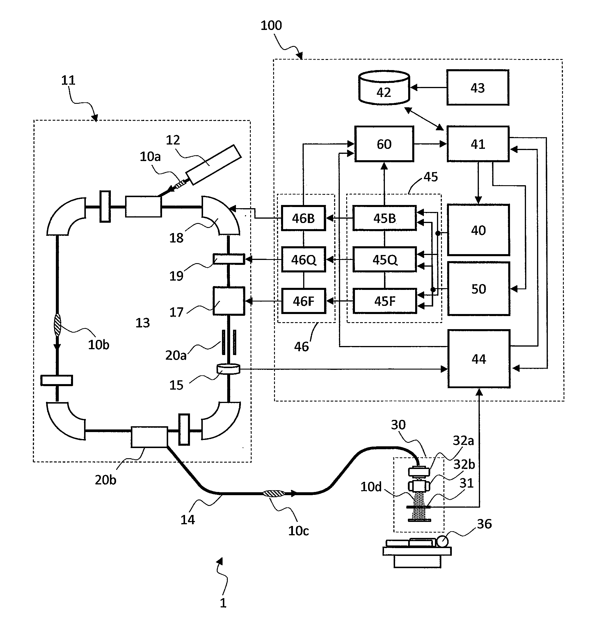
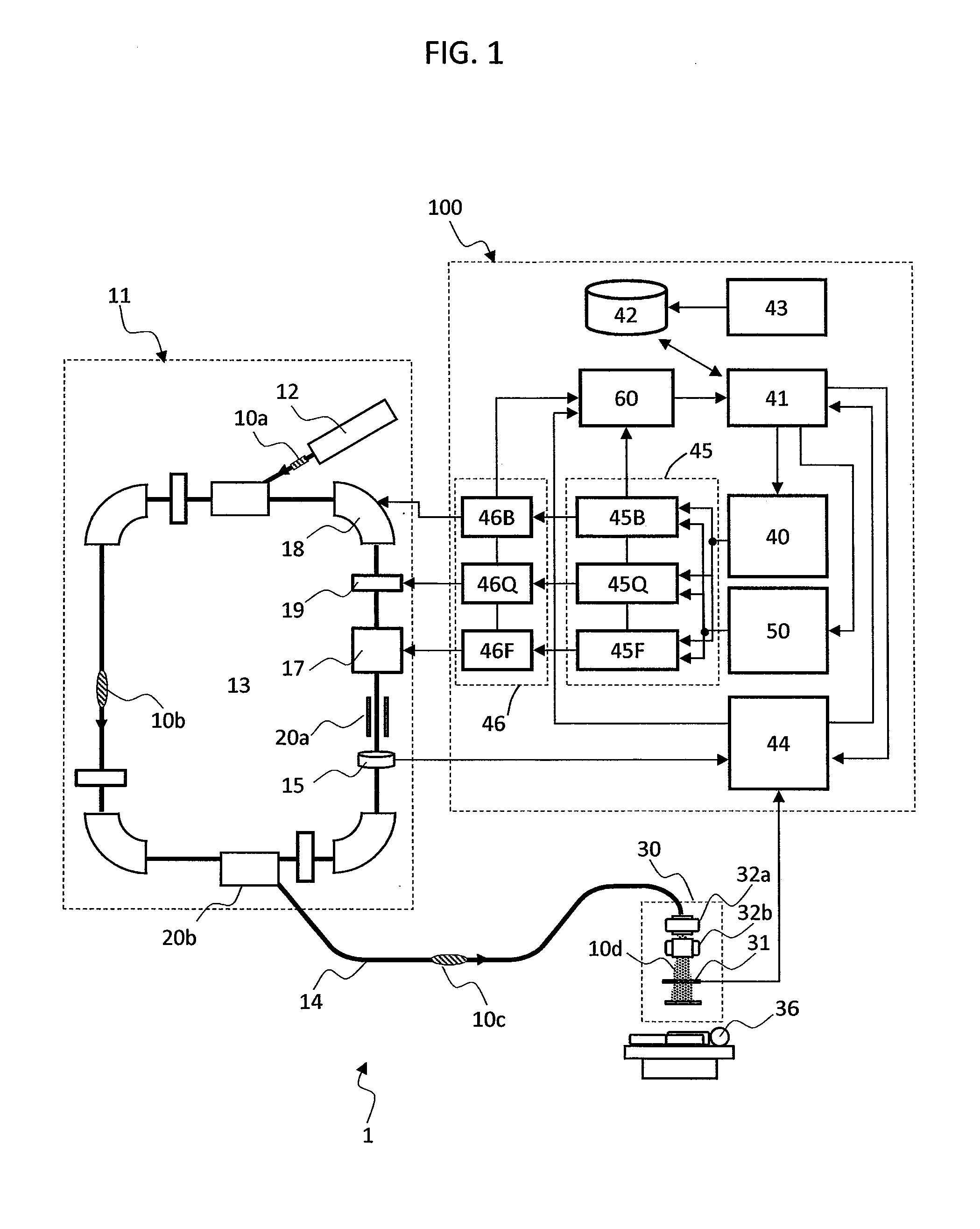
[0032]FIG. 1 is a diagram showing a configuration of a particle beam system according to a preferred embodiment of the present invention.

[0033]As shown in FIG. 1, the particle beam system 1 according to the present embodiment includes an ionized particle accelerator 11, a beam transport device 14, and an irradiation field forming device (an ionized-particle beam irradiation device; hereinafter, referred to simply as the irradiation device) 30. The beam transport device 14 provides communication between the ionized particle accelerator 11 and the irradiation device 30 placed inside a treatment room.

[0034]The ionized particle accelerator 11 includes an ion source (not shown), a pre-accelerator 12, and a synchrotron accelerator 13. The ion source is connected to the pre-accelerator 12, and the pre-accelerator 12 is connected to the synchrotron accelerator 13. The pre-accelerator 12 a...


PUM


Abstract

To reduce the number of steps of generating control pattern data needed for achieving beam irradiation with desired energy in the beam extraction from a synchrotron accelerator, a data generator 41 divides adjusted control pattern data, defines the divided data intervals as data modules, and reuses each of the data modules to generate new control pattern data. For extraction energy level changes, which are characteristic of multi-energy extraction, energy change control pattern data is generated based on the extraction pattern data before an energy level change and the extraction pattern data after the energy level change by using an interpolation function thereby to allow the control pattern data to be automatically generated. Effects of residual magnetic fields are calculated in advance, and then adjustment values that allow for the effects of the residual magnetic fields are incorporated into the control pattern data and operation is controlled.

Description

BACKGROUND OF THE INVENTION[0001]1. Field of the Invention[0002]The present invention relates to particle beam systems suitable for particle beam therapy using such an ionized particle beam (ion beam) as of protons or heavy ions. More particularly, the invention is directed to a particle beam system that accelerates and extracts an ion beam using a synchrotron accelerator, and to a method of generating operation control pattern data used to control devices constituting the synchrotron accelerator.[0003]2. Description of the Related Art[0004]Particle beam therapy, a treatment performed upon the cancer in a patient by irradiating the affected region with such an ion beam as of protons or heavy ions, is known as radiation therapy for cancer. Useable methods for ion beam irradiation include such a scanning irradiation method that is disclosed in REVIEW OF SCIENTIFIC INSTRUMENTS, VOLUME 64, NUMBER 8 (AUGUST 1993), pp. 2074-2093 (hereinafter referred to as Non-Patent Document 1).[0005]In ...

Claims


Application Information

Patent Timeline
IPC IPC(8): H05H13/04
CPCH05H13/04H05H7/04H05H2007/008
Inventor ARITA, HARUKITAKEDA, MOEMI
Owner HITACHI LTD
Why Eureka
Try Eureka