Radiation focal position detecting method, radiation detecting apparatus and radiation tomographic imaging apparatus

a radiation detecting and focal position technology, applied in tomography, instruments, nuclear engineering, etc., can solve the problems of increasing the adverse effect of the position error in the radiation focal point, the difficulty of detecting the position of the radiation focal point and the amount of movement thereof with sufficient resolution, and the effect of high resolution

Active Publication Date: 2014-06-05
GENERAL ELECTRIC CO
View PDF7 Cites 7 Cited by
  • Summary
  • Abstract
  • Description
  • Claims
  • Application Information

AI Technical Summary

Benefits of technology

[0006]The systems and methods disclosed herein detect a positional displacement of a foc...

Problems solved by technology

A position error in the radiation focal point may affect the geometry of a data acquisition system, thus resulting in the occurrence of serious artifacts in a high resolution region of the acquired image.
In this case, the adverse effect due to the position error in the radiation focal point b...

Method used


Image

  • Radiation focal position detecting method, radiation detecting apparatus and radiation tomographic imaging apparatus
  • Radiation focal position detecting method, radiation detecting apparatus and radiation tomographic imaging apparatus
  • Radiation focal position detecting method, radiation detecting apparatus and radiation tomographic imaging apparatus

Examples


first embodiment

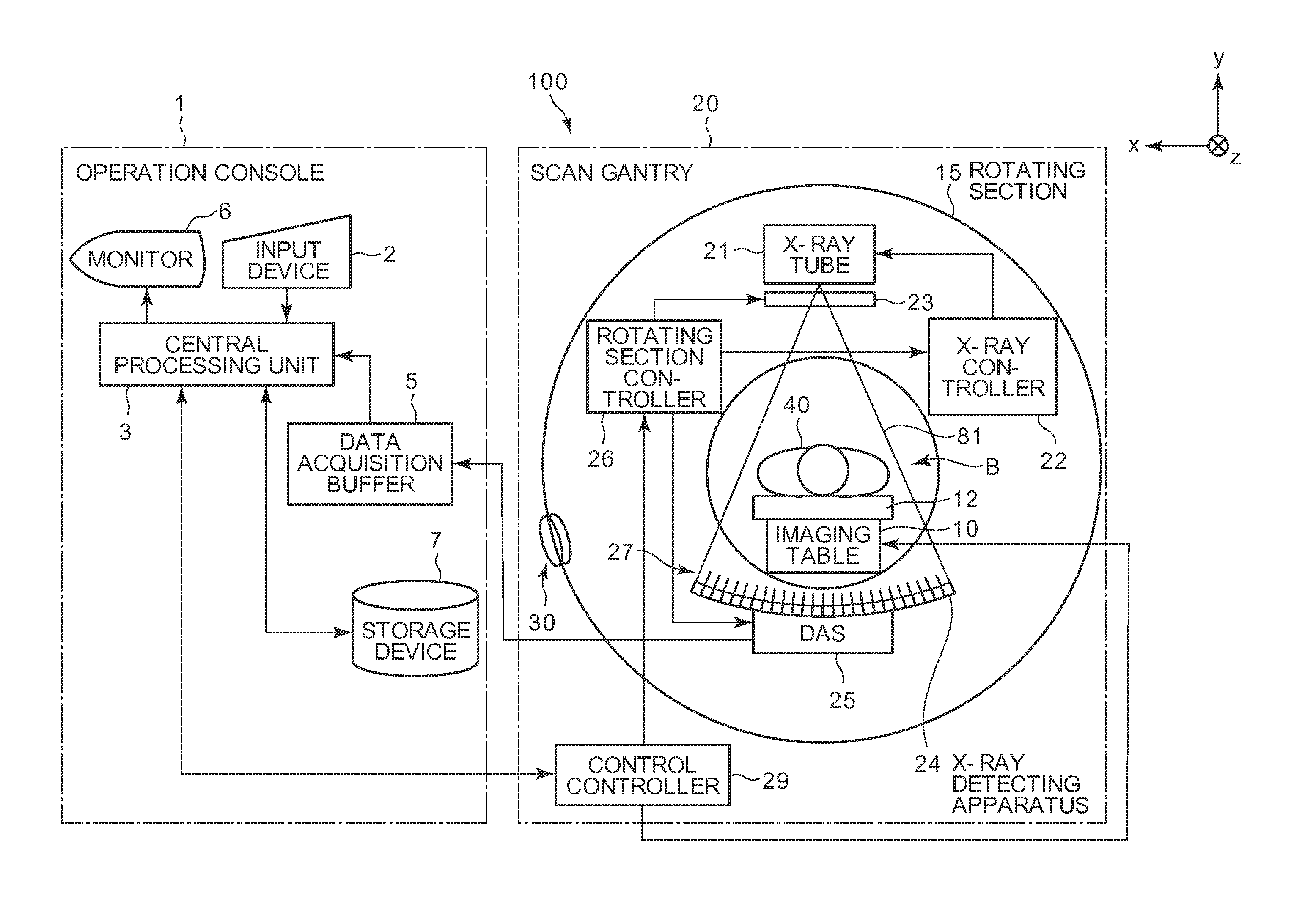
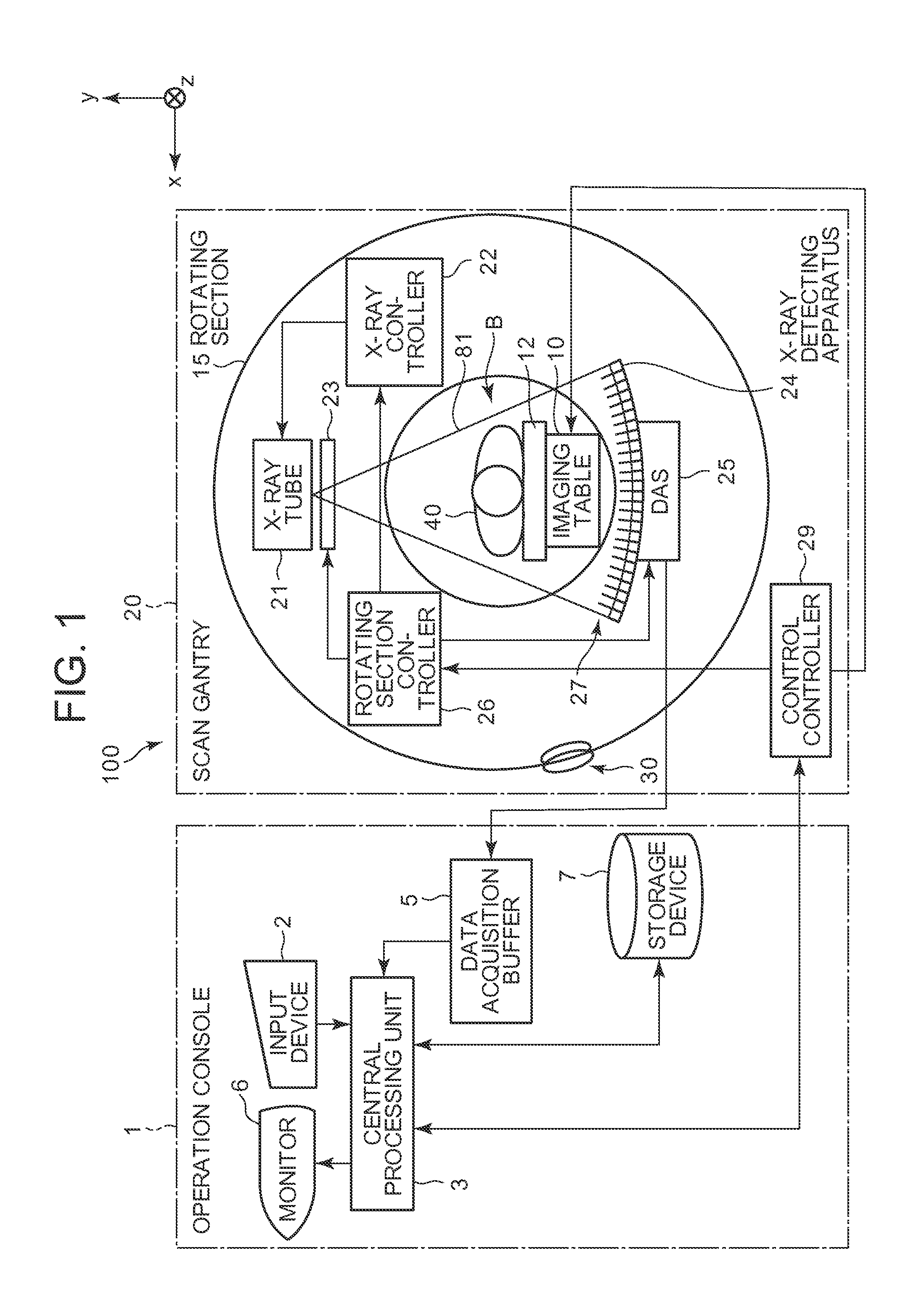
[0039]FIG. 1 is a diagram schematically showing a configuration of an X-ray CT apparatus according to a first embodiment.

[0040]The X-ray CT apparatus 100 is equipped with an operation console 1, an imaging table 10 and a scan gantry 20.

[0041]The operation console 1 is equipped with an input device 2 which accepts an input from an operator, a central processing unit 3 which performs control of respective parts for performing subject's imaging, a data process for generating an image, etc., a data acquisition buffer 5 which acquires or collects data acquired by the scan gantry 20, a monitor 6 which displays each image thereon, and a storage device 7 which stores programs, data, etc. therein.

[0042]The imaging table 10 is equipped with a cradle 12 which inserts and draws a subject 40 into and from an opening B of the scan gantry 20 with the subject 40 placed thereon. The cradle 12 is elevated and linearly moved horizontally by a motor built in the imaging table 10. Incidentally, in the p...

second embodiment

[0082]FIGS. 9A and 9B are partly enlarged diagrams of an X-ray detecting apparatus according to a second embodiment. FIG. 9A is a diagram (front diagram) as viewed from the X-ray tube 21 side, and FIG. 9B is a diagram (side diagram) as viewed in a z direction.

[0083]Incidentally, here, as shown in FIGS. 9A and 9B, a detection surface of a detecting element 271 (1, A2) and a detection surface of a detecting element (2, A2) are merged with each other to take on a first detection surface D1 (detection surface of first detecting element region). A detection surface of a detecting element 271 (1, A1) and a detection surface of a detecting element 271 (2, A1) are merged with each other to assume a second detection surface D2 (detection surface of a second detecting element region). A detection surface of a detecting element 271 (1, B1) and a detection surface of a detecting element (2, B1) are merged with each other to take on a third detection surface D3 (detection surface of first detect...


PUM


Abstract

A radiation focal position detecting method for detecting a positional displacement of a focal point of a radiation source in a radiation tomographic imaging apparatus is provided. The method includes providing a radiation absorber that covers parts of first and second detecting element regions, the parts lying on mutually adjoining sides of the first and second detecting element regions in a radiation detector including a plurality of detecting elements arranged in channel and slice directions, and specifying, based on intensities of radiation detected by the detecting elements in the first and second detecting element regions, a position of the focal point or an amount of movement of the focal point from a reference position.

Description

BACKGROUND OF THE INVENTION[0001]The present invention relates to a radiation focal position detecting method, a radiation detecting apparatus and a radiation tomographic imaging apparatus, and more specifically to a technology which detects a positional displacement of a radiation focal point of a radiation source in high resolution.[0002]In a radiation tomographic imaging apparatus having a multi-detector, such as a multi-slice X-ray CT apparatus or the like, the accuracy of position of a radiation focal point of a radiation source is very important in maintaining an acquired image in high quality. A position error in the radiation focal point may affect the geometry of a data acquisition system, thus resulting in the occurrence of serious artifacts in a high resolution region of the acquired image. In a recent radiation detecting apparatus in particular, a two-dimensional collimator having collimator plates arranged in channel and slice directions are often used to reduce scatter...

Claims


Application Information

Patent Timeline
IPC IPC(8): G01T1/29
CPCA61B6/032A61B6/4078A61B6/4233A61B6/4291A61B6/5205A61B6/58G06T11/005
Inventor KUROCHI, HARUOABDELAZIZ, IKHLEF
Owner GENERAL ELECTRIC CO
Why Eureka
Try Eureka