Eureka AIR delivers breakthrough ideas for toughest innovation challenges, trusted by R&D personnel around the world.

Expandable Cage for the Intercorporal Fusion of Lumbar Vertebrae

a cage and lumbar vertebrae technology, applied in the field of spine surgery, can solve the problems of difficult to clearly control the degree of expansion achieved and monitor, and the need for the spacer to be placed, and achieve the effect of reducing the risk of fractur

Active Publication Date: 2014-06-05
TAURUS GMBH & CO KG
View PDF3 Cites 60 Cited by
  • Summary
  • Abstract
  • Description
  • Claims
  • Application Information

AI Technical Summary

Benefits of technology

The present invention is an expandable cage that can be easily and quickly brought into its expanded state to support the load transfer in intercorporal fusion of lumbar vertebrae. It is designed to ensure high reliability and resistance to failure.

Problems solved by technology

Although this known cage offers the above-mentioned advantage owing to its expandability, the necessary procedure of inserting the spacer disc as far as the end position for expanding the cage is, however, complex and requires a high level of ability and skill on the part of the surgeon.
It remains equally difficult to clearly control the degree of expansion which is achieved and to monitor whether the end position has been reliably reached.
Although more simple and rapid adjustability of the cage into the expanded position can be achieved in this way, the limited contact surface between the expansion element and the arms in the expanded state means that the load-bearing capacity is low, especially since, when subjected to a load, it is not possible to reliably prevent the expansion element from rotating about the axis of rotation and the arms from tilting about axes lying parallel to the axis of rotation.
It is also not possible to rule out the expansion element itself tilting about a transverse axis which is perpendicular to the longitudinal axis of the cage.

Method used


Image

  • Expandable Cage for the Intercorporal Fusion of Lumbar Vertebrae
  • Expandable Cage for the Intercorporal Fusion of Lumbar Vertebrae
  • Expandable Cage for the Intercorporal Fusion of Lumbar Vertebrae

Examples


Embodiment Construction

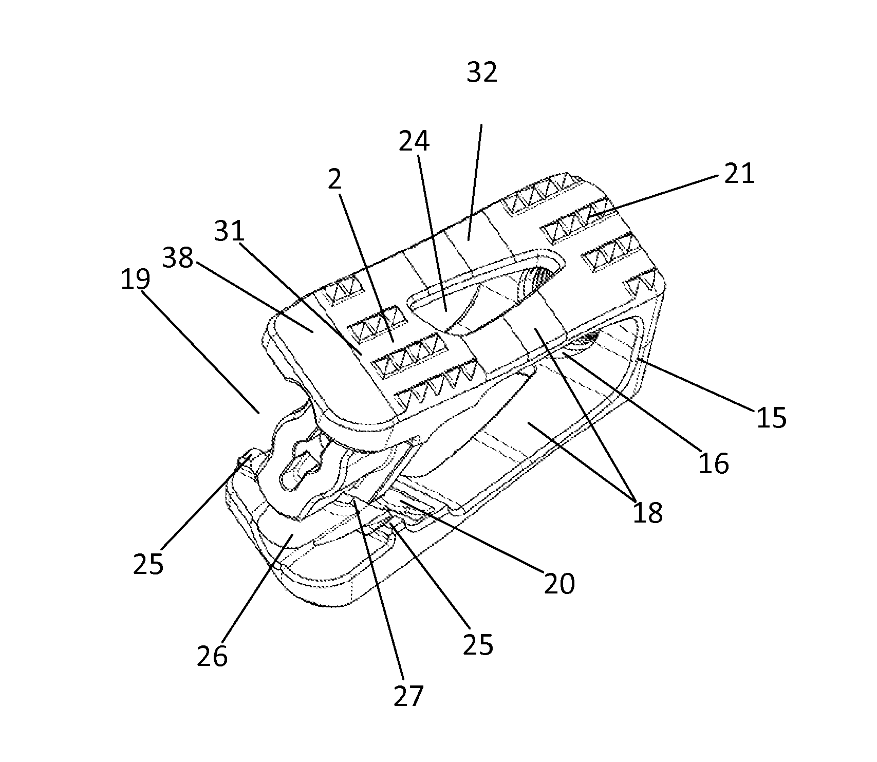
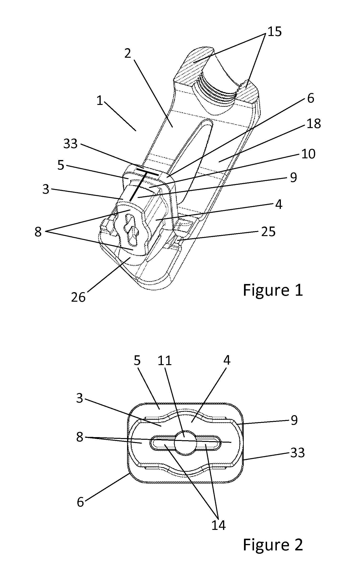
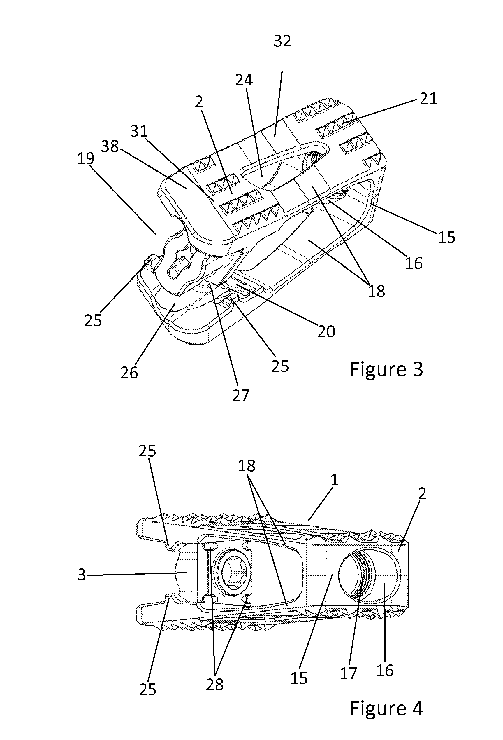
[0043]FIG. 1 shows a horizontal medial longitudinal section through the monolithic main body (2) of a cage (1) according to the invention, with an expansion element (3) inserted in an expanded position on the lower arm (18). The expansion element (3) has a rotatable elongated cylindrical base body (4) on the rear end of which a rectangular plate (5) having rounded edges (6) extending in the longitudinal direction of the cage (1) is integrally formed in one piece. Two one-piece opposing ribs (8), whereof the respective radial bearing surfaces (9) terminate at the shorter narrow sides (33) of the rectangular plate (5), are constructed from the plate (5) as far as the front end of the base body (4) of the expansion element (3). The width of the ribs (8) almost reaches the diameter of the cylindrical base body (4). Respective rectangular grooves (10) are incorporated in the ribs (8) so that they extend parallel to the shorter narrow side (33) of the rectangular plate (5) and a lateral s...


PUM


Abstract

An expandable cage for intercorporal fusion of lumbar vertebrae comprises a main body with two expandable parallel arms. Each arm has a supporting surface pointing outside and configured to contact an adjacent vertebral body, a groove pointing inside and extending along a transverse direction, and a channel pointing inside and extending along a longitudinal direction. An expansion element is instrument actuated and presses the arms apart expanding the cage. The expansion element is between the arms and comprises a cylindrical base body, two opposing radially aligned ribs on the base body, and a rectangular plate. Both the base body and ribs have curved, pair-wise opposed bearing surfaces. Depending on the cage's expansion state, either the base body bearing surfaces or the rib bearing surfaces contact channels provided in the arms, while the plate engages in the grooves of the arms.

Description

CROSS-REFERENCE TO RELATED APPLICATIONS[0001]This application claims benefit of German patent application 10 2012 023 042.7 filed on Nov. 26, 2012. The full disclosure of this earlier application is incorporated herein by reference.BACKGROUND OF THE INVENTION[0002]1. Field of the Invention[0003]The present invention relates to a cage for the intercorporal fusion of lumbar vertebrae.[0004]The technical field to which the present invention relates is spinal surgery. To treat people with degenerative changes to the lumbar vertebral column, in which a mono- or multi-segment fusion is indicated, but also in cases which are aimed at a decompression of the neural structures, two operating techniques in particular have proven effective, which enable intervention without additional trans-abdominal access. In the so-called PLIF operating technique (Posterior Lumbar Intervertebral Fusion) two so-called cages are preferably implanted for each disc space by way of posterior access. The implanted...

Claims


Application Information

Patent Timeline
Patent Type & Authority Applications(United States)
IPC IPC(8): A61F2/44
CPCA61F2/447A61F2/442A61F2/4611A61F2002/30151A61F2002/30153A61F2002/30158A61F2002/30166A61F2002/30266A61F2002/30365A61F2002/3039A61F2002/30397A61F2002/30401A61F2002/30482A61F2002/30484A61F2002/30515A61F2002/30518A61F2002/3054A61F2002/30556A61F2002/30593A61F2002/30624A61F2002/30774A61F2002/30777A61F2002/30785A61F2002/30789A61F2002/30822A61F2002/30843A61F2002/30897A61F2002/4629A61F2/44A61F2/4455
Inventor PABST, MARTINTADDIA, LINOPANDORF, THOMASSPITSENBERG, MARCUSKOHLBRENNER, CHRISTOPH
Owner TAURUS GMBH & CO KG
Why Eureka
Eureka Blog
Learn More