
Method and Device for Stretch Blow Molding or Blow Molding and Filling Sterile Containers

Active Publication Date: 2011-03-17
KRONES AG
View PDF14 Cites 34 Cited by
  • Summary
  • Abstract
  • Description
  • Claims
  • Application Information

AI Technical Summary

Benefits of technology

[0008]By carrying out the main sterilization treatment at the preforms, of which the high-temperature surface of the preform to be treated is relatively small and rugged, the operation can be more aggressive and thus efficient, so that the containers coming out of the blow module already fulfill a largely sterile standard and the subsequent sterilization treatment can be relatively simple, to also make the containers really sterile, i.e. that in the subsequent sterilization treatment, at most only dust and possibly residues of the medium from the main sterilization treatment must be removed. However, the risk of residues from the main sterilization treatment remains extremely low, as in the blow module a multiple exchange of the air volume takes place which also removes possibly existing residual components. As due to the ruggedness of the preforms, e.g. if a gaseous or liquid medium is used for the sterilization treatment, high temperatures and pressures can be employed in the operation, only a relatively short transport section is required for the main sterilization treatment. For the subsequent sterilization treatment of the containers carried out as a precaution, too, only little time and equipment are required, for example, no blow-out stars or processing stars with lifting controls are required, which are indispensable if exclusively the containers are subjected to sterilization treatment. Thus, the efforts as to the equipment and thus also to the control system for performing the method can be reduced.
[0025]To minimize the operational risk of the device, it can be furthermore appropriate for at least the energy beam generator, or even the complete module, to be arranged in a shielded radiation maze in the main sterilization module and / or in the subsequent sterilization module working with energy beams.

Problems solved by technology

However, the risk of residues from the main sterilization treatment remains extremely low, as in the blow module a multiple exchange of the air volume takes place which also removes possibly existing residual components.
The omission of blow-out stars or processing stars with lifting controls reduces the efforts as to the equipment and control system.

Method used


Image

  • Method and Device for Stretch Blow Molding or Blow Molding and Filling Sterile Containers
  • Method and Device for Stretch Blow Molding or Blow Molding and Filling Sterile Containers
  • Method and Device for Stretch Blow Molding or Blow Molding and Filling Sterile Containers

Examples


Embodiment Construction

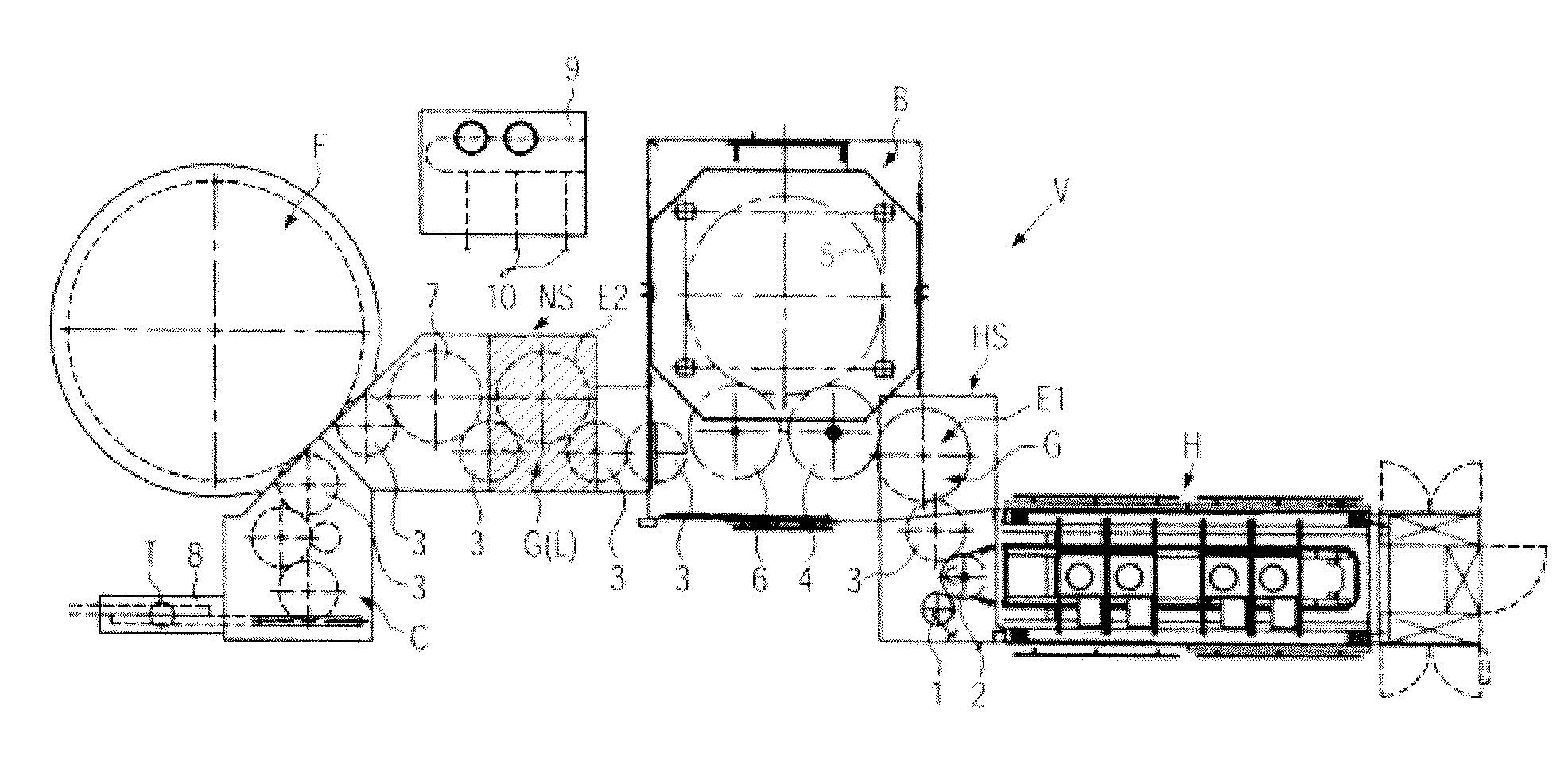
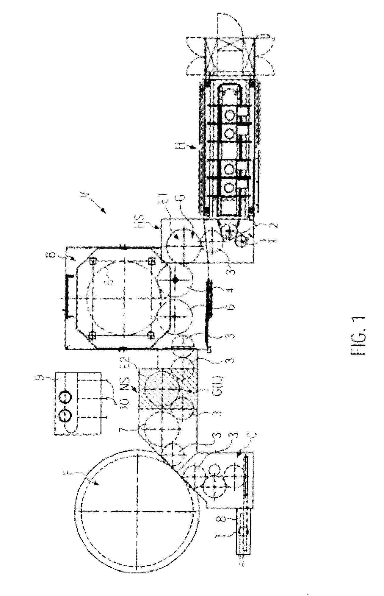
[0036]FIG. 1 shows a device V for blow molding or stretch blow molding and filling sterile containers T. Preforms of thermoplastic material are supplied to a heating device H via a transport star 1. The preforms are introduced into the heating device H by this transfer star 1 and provided therein with a predetermined temperature profile, before they are subsequently brought to a main sterilization module HS via a transfer star 3 in which a main sterilization operation is performed at the preforms. The main sterilization module HS is inserted between the transport device 3 and a further transport device 4 of a blow module B in which a blow rotor 5 is arranged with non-depicted blow molds. As indicated by the solid outlines of the blow module B, the blow module B can be located at least in the region of the blow rotor 5 in a clean room environment. The blow molded or stretch blow molded containers T are transferred via a further transport device 6 to a transport device 3 and are broug...


PUM

PropertyMeasurementUnit
Pressureaaaaaaaaaa

Abstract

A method for blow molding and filling sterile containers of preforms in a container treatment device containing a blow module, in which the preforms are transferred from a heating device to the blow module via transport devices, and the containers are transported to a filling machine and filled, where a sterilization treatment is performed each at the preforms and the containers, a main sterilization treatment is performed at the preforms between the heating device and the blow module, and only a subsequent sterilization treatment is performed at the containers on the transport path to the filling machine. Further, a device having a main sterilization module between the heating device and the blow module, and a subsequent sterilization module between the blow module and the filling machine.

Description

CROSS-REFERENCE TO RELATED APPLICATION[0001]The present application claims the benefit of priority of German Application No. 102009041215.8, filed Sep. 11, 2009. The entire text of the priority application is incorporated herein by reference in its entirety.FIELD OF THE DISCLOSURE[0002]The disclosure relates to a method and to a device for stretch blow molding or blow molding and filling of sterile containers, such as in bottling operations.BACKGROUND[0003]In the method known from DE 10 2006 053 193 A, the containers blow molded or stretch blow molded from the preforms are sterilized on the transport path between the blow module and the filling machine. In the process, first a sterilization treatment is performed on the inner surfaces, then a sterilization treatment is performed on the outer surfaces in an external tunnel, and finally sweeping with sterile air is performed. The apparatus and control complexity for the sterilization treatment is high. For example, treatment stars wit...

Claims


Application Information

Patent Timeline
IPC IPC(8): B65B3/02B65B47/00
CPCB29C49/42B29C49/46B29C2049/4679B67C2003/227B65B55/027B65B55/10B29C2049/4697B29C49/42418B29C49/42808
Inventor ROITHMEIER, STEFANSTOIBER, CHRISTIANBRAUN, FRANZDAHMEN, MICHAELENGELHARD, PATRICKHOLLRIEGL, THOMASLAUMER, ROLLANDSOLLNER, JURGENNEUBAUER, MICHAEL
Owner KRONES AG
Learn More