Nozzle with reciprocating plunger

a technology of reciprocating plunger and nozzle, which is applied in the direction of instruments, television systems, sensing by electromagnetic radiation, etc., can solve the problems of major complication in the design of high speed and page width printheads, heat generation, etc., and achieves high speed operation, energy saving, and simple actuation mechanism

Inactive Publication Date: 2009-12-08
SILVERBROOK RES PTY LTD +1
View PDF30 Cites 36 Cited by
  • Summary
  • Abstract
  • Description
  • Claims
  • Application Information

AI Technical Summary

Benefits of technology

[0017]Ejecting ink from the nozzle with a reciprocating plunger and simple actuating mechanism is energy efficient and offers high speed o

Problems solved by technology

Each technology may have its own advantages and disadvantages in the areas of cost, speed, quality, reliability, power usage, simplicity of c

Method used


Image

  • Nozzle with reciprocating plunger
  • Nozzle with reciprocating plunger
  • Nozzle with reciprocating plunger

Examples


example method

of Fabrication

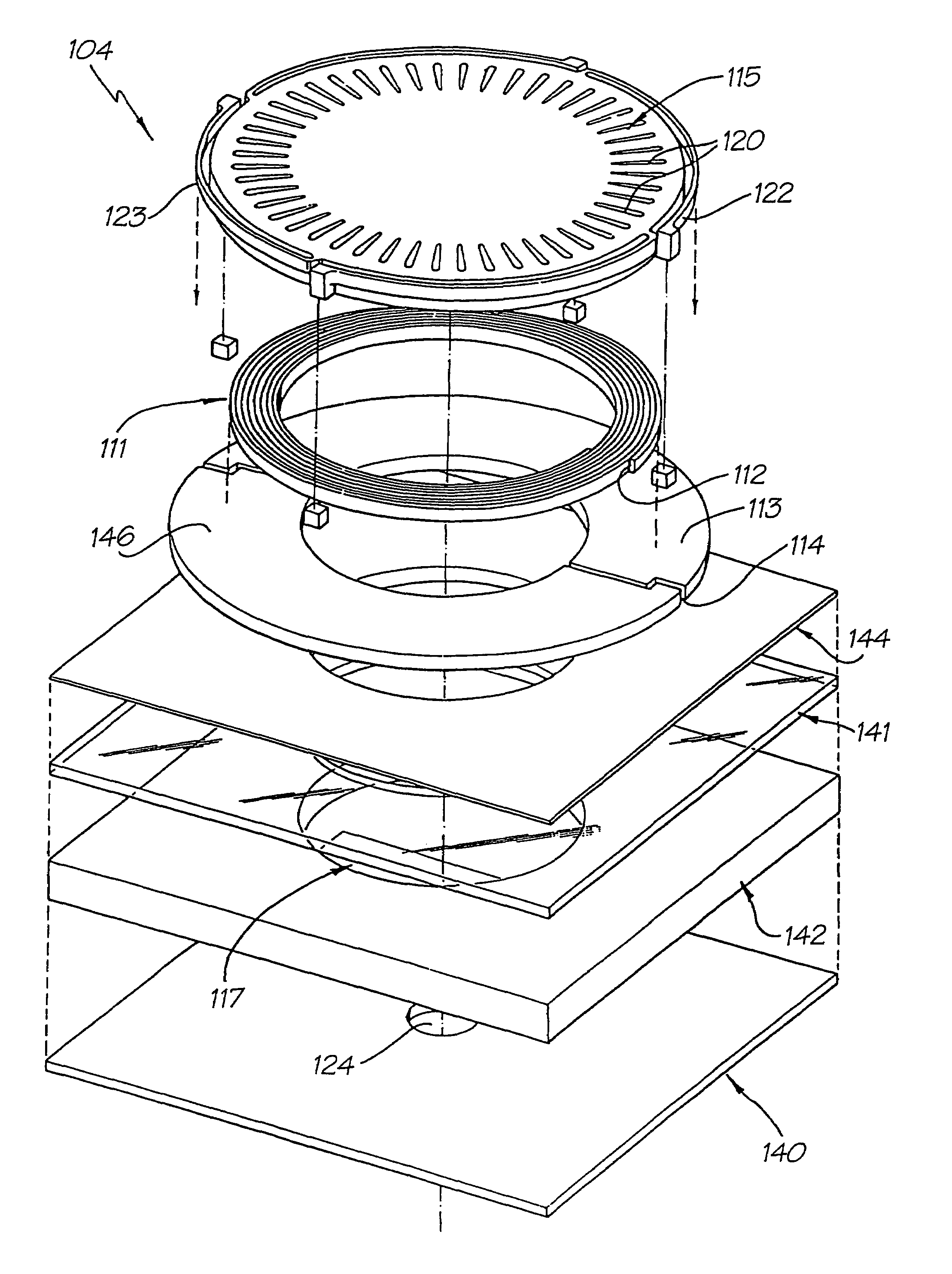
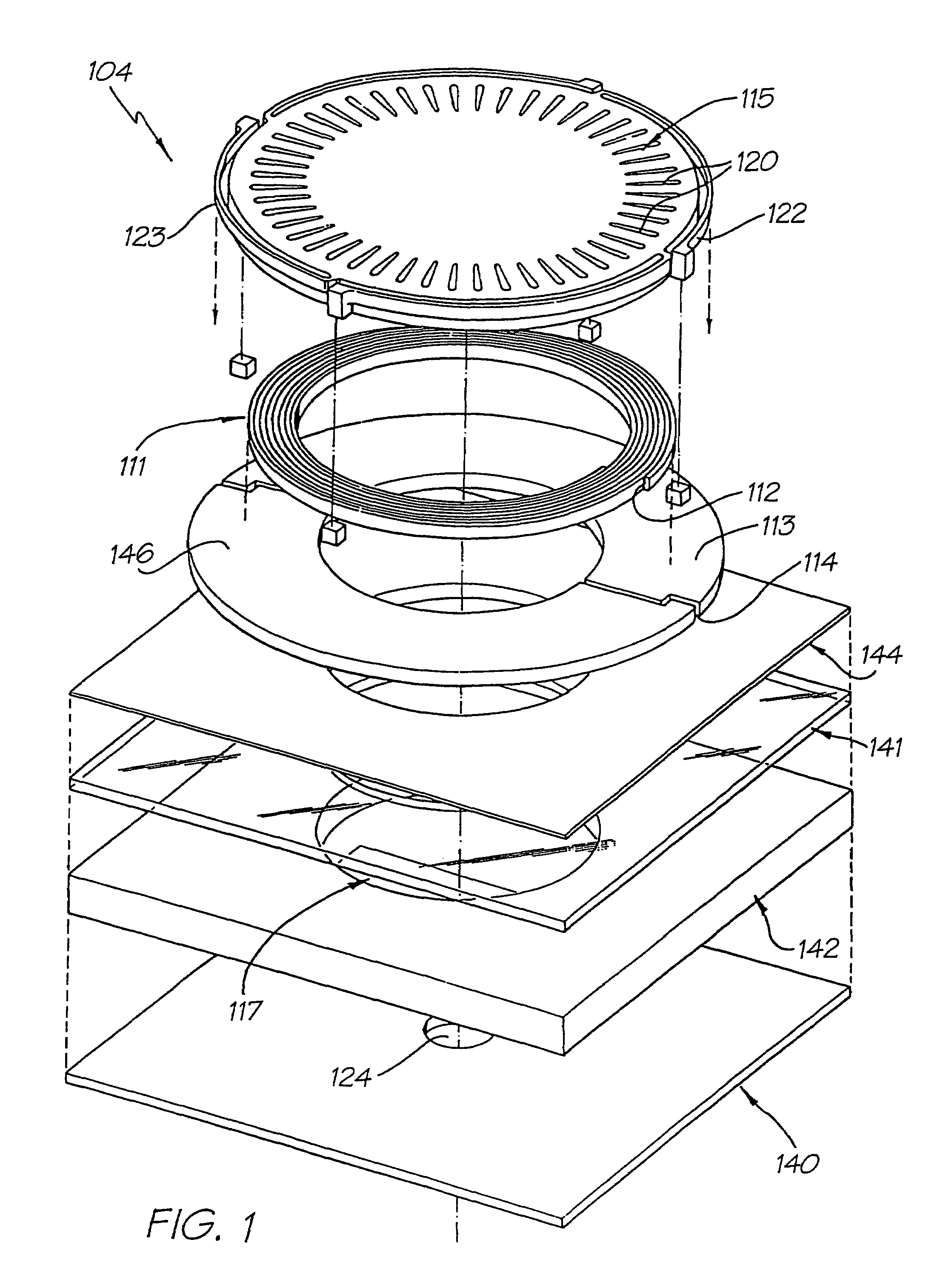
[0726]The print head is fabricated from two silicon apparatus wafers. A first wafer is used to fabricate the nozzle apparatus (the print head wafer) and a second wafer is utilized to fabricate the various ink channels in addition to providing a support means for the first channel (the Ink Channel Wafer). FIG. 114 is an exploded perspective view illustrating the construction of the ink jet nozzle apparatus 701 on a print head wafer. The fabrication process proceeds as follows:

[0727]Start with a single silicon wafer, which has a buried epitaxial layer 721 of silicon which is heavily doped with boron. The boron should be doped to preferably 1020 atoms per cm3 of boron or more, and be approximately 3 μm thick. A lightly doped silicon epitaxial layer 722 on top of the boron doped layer 721 should be approximately 8 μm thick, and be doped in a manner suitable for the active semiconductor device technology chosen. This is the starting point for the print head wafer. The wafer...

example

Basic Fabrication Sequence

[1430]Two wafers are required: a wafer upon which the active circuitry and nozzles are fabricated (the print head wafer) and a further wafer in which the ink channels are fabricated. This is the ink channel wafer. One form of construction of printhead wafer will now be discussed with reference to FIG. 449 which illustrates an exploded perspective view of a single ink jet nozzle constructed in accordance with a preferred embodiment.

[1431]1) Starting with a single crystal silicon wafer, which has a buried epitaxial layer 2316 of silicon which is heavily doped with boron. The boron should be doped to preferably 1020 atoms per cm3 of boron or more, and be approximately 3 micron thick. The lightly doped silicon epitaxial layer 2315 on top of the boron doped layer should be approximately 8 micron thick, and be doped in a manner suitable for the active semiconductor device technology chosen. This is the printhead wafer. The wafer diameter should preferably be the ...


PUM


Abstract

An inkjet nozzle with a chamber defined by a plunger spaced from an ejection nozzle. An actuator moves the plunger towards the nozzle to eject drops of ink. Ejecting ink from the nozzle with a reciprocating plunger and simple actuating mechanism is energy efficient and offers high speed operation. With relatively low power consumption, the printhead can be easily extended to pagewidth.

Description

CROSS-REFERENCES TO RELATED APPLICATIONS[0001]This is a CIP Application of U.S. application Ser. No. 10 / 407,212, filed on Apr. 7, 2003, now U.S. Pat. No. 7,416,280 which is a Continuation Application of U.S. application Ser. No. 09 / 113,122, filed on Jul. 10, 1998, now issued as U.S. Pat. No. 6,557,977.[0002]The following Australian provisional patent applications are hereby incorporated by reference. For the purposes of location and identification, US patents / patent applications identified by their US patent / patent application serial numbers are listed alongside the Australian applications from which the US patents / patent applications claim the right of priority.[0003]US PATENT / PATENTCROSS-REFERENCEDAPPLICATION (CLAIMINGAUSTRALIAN PRO-RIGHT OF PRIORITYVISIONAL PATENTFROM AUSTRALIAN PRO-DOCKETAPPLICATION NO.VISIONAL APPLICATION)NO.PO799109 / 113,060ART01PO85056,476,863ART02PO798809 / 113,073ART03PO93956,322,181ART04PO80176,597,817ART06PO80146,227,648ART07PO802509 / 112,750ART08PO80326,690,...

Claims


Application Information

Patent Timeline
IPC IPC(8): B41J2/04B41J2/045B41J2/14B41J2/16B41J2/165B41J2/175B41J3/42B41J3/44B41J11/00B41J11/70B41J15/04G06F1/16G06F21/00G06K1/12G06K7/14G06K19/06G06K19/073G07F7/08G07F7/12H04N1/00H04N1/21H04N1/32H04N5/225H04N5/262
CPCB41J2/14314H04N5/2628B41J2/1623B41J2/1626B41J2/1628B41J2/1629B41J2/1631B41J2/1632B41J2/1635B41J2/1637B41J2/1639B41J2/1642B41J2/1643B41J2/1645B41J2/1646B41J2/1648B41J2/17513B41J3/445B41J11/0005B41J11/70B41J15/04G06F21/79G06F21/86G06K1/121G06K7/14G06K7/1417G06K19/06037H04N5/225B41J2/14427B41J2/16585B41J2/17596B41J2002/041B41J2002/14346B41J2002/14435B41J2202/21B42D2035/34G06F2221/2129H04N23/00B41J2/14
Inventor SILVERBROOK, KIA
Owner SILVERBROOK RES PTY LTD
Why Eureka
Try Eureka