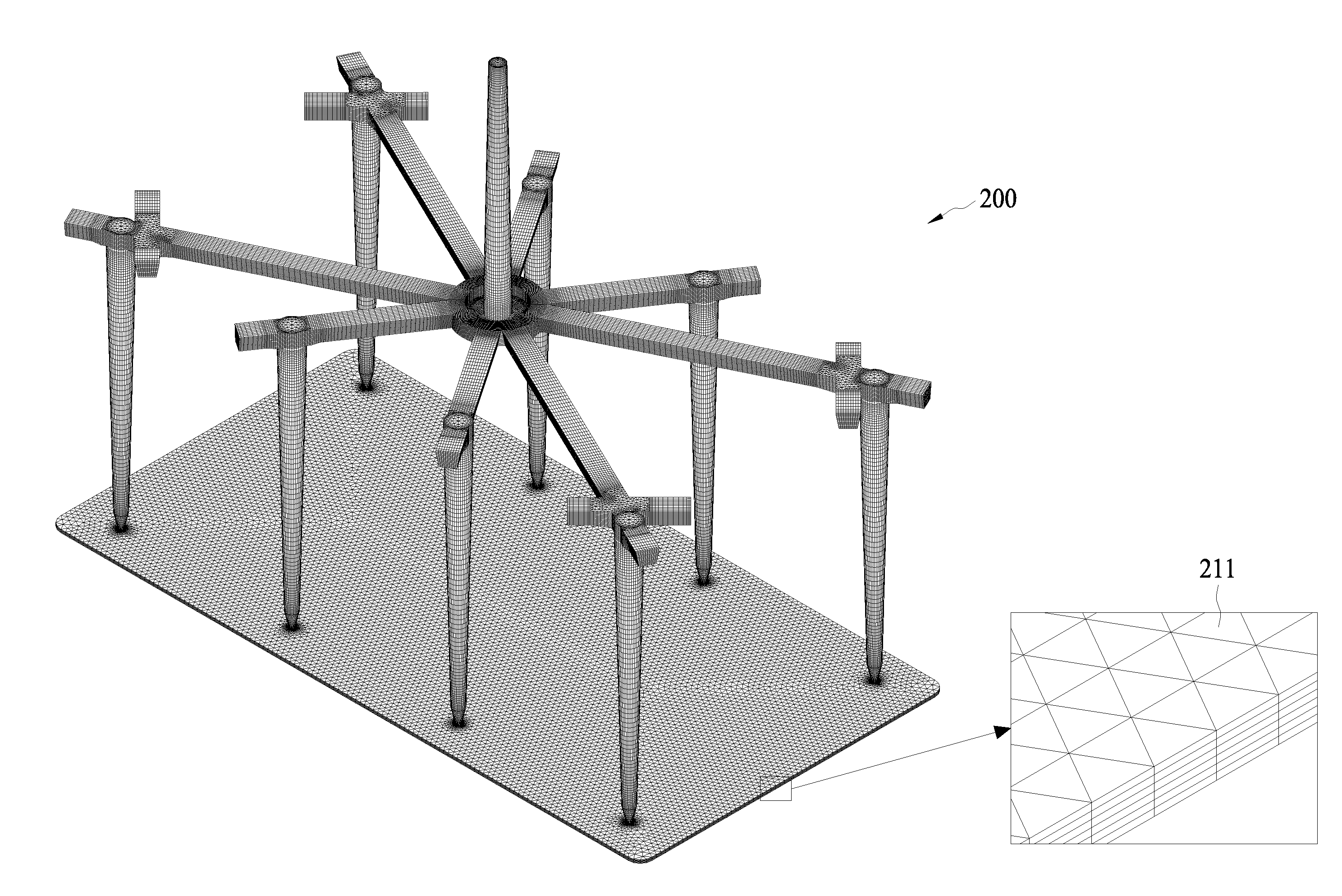
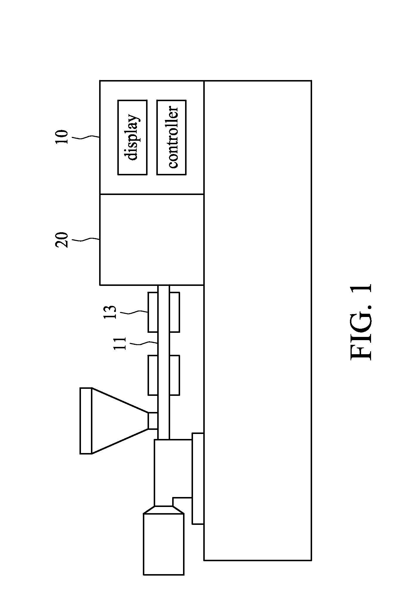
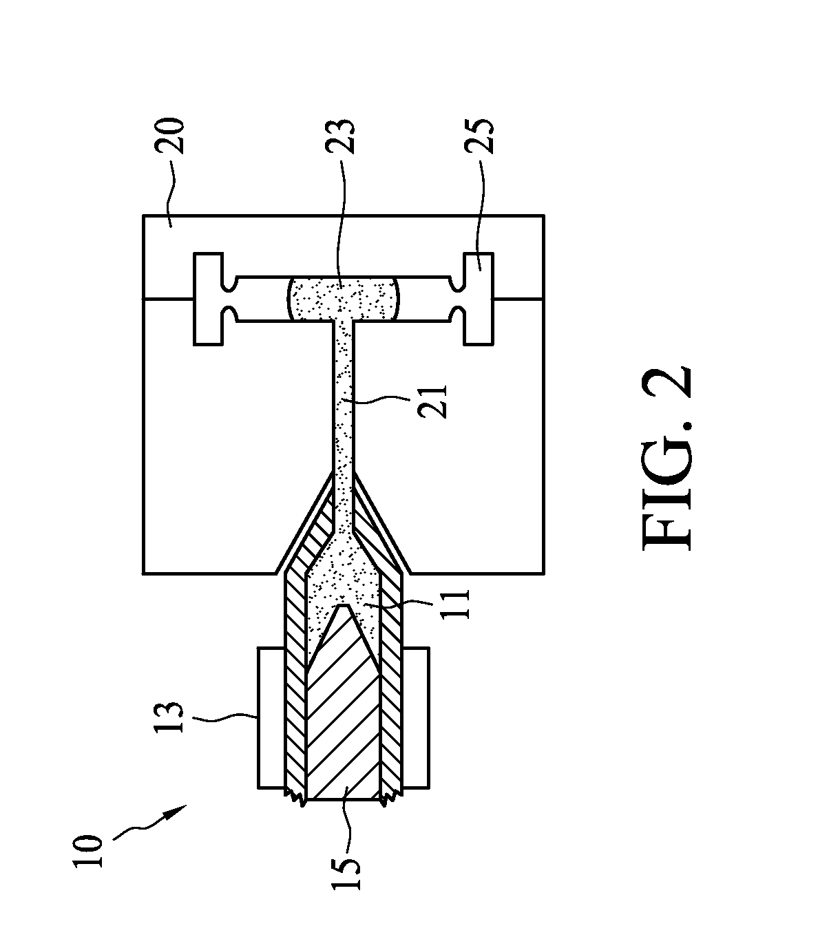
Predicting Shrinkage of Injection Molded Products with Viscoelastic Characteristic

a technology of viscoelastic characteristic and injection molding, which is applied in the field of computerimplemented method and non-transitory computer medium for predicting shrinkage of injection molding products, can solve the problems of a large number of trial molding operations and a long setting time, and achieve the effects of reducing molding pressure and molding temperature, increasing shear viscosity of molding fluid, and increasing molding fluid shear ra

Active Publication Date: 2014-06-05
CORETECH SYST
View PDF0 Cites 4 Cited by
  • Summary
  • Abstract
  • Description
  • Claims
  • Application Information

AI Technical Summary

Benefits of technology

[0007]In accordance with some embodiments of the present disclosure, a computer-implemented method for calculating a shrinkage of a molding product comprises a step of using a computer processor to calculate a molding pressure of a molding fluid in a molding cavity by taking into consideration an increase of a shear viscosity of the molding fluid by a decrease of a shear rate. In some embodiments, the calculating of the shrinkage further takes into consideration a variation of a specific volume of the molding fluid as the molding pressure and a molding temperature decrease.
[0008]In accordance with some embodiments of the present disclosure, a non-transitory computer medium contains computer instructions stored therein for causing a computer processor to perform operations for calculating a shrinkage of a molding product, and the operations comprise a step of calculating the shrinkage of the molding product from a molding fluid by taking into consideration an increase of a shear viscosity of the molding fluid by a decrease of a shear rate. In some embodiments, the calculating of the shrinkage further takes into consideration a variation of a specific volume of the molding fluid as the molding pressure and a molding temperature decrease.
[0009]The present disclosure provides a VE-Cross-WLF viscosity model for describing the elastic characteristic of the molding fluid like the solid in addition to the viscous characteristic of the molding fluid. The prediction of the molding pressure by using a Cross-WLF viscosity model deviates from the experimental data significantly, i.e., underestimating the filling pressure. In contrast, the prediction of the molding pressure by using the proposed VE-Cross-WLF viscosity model of the present disclosure substantially matches with the experimental data.

Problems solved by technology

In general, the setting of molding conditions in an injection molding machine requires a large number of trial molding operations and a long setting time because the setting work greatly depends on the know-how and experience of an operator, and various physical values affect one another as well.

Method used


Image

  • Predicting Shrinkage of Injection Molded Products with Viscoelastic Characteristic
  • Predicting Shrinkage of Injection Molded Products with Viscoelastic Characteristic
  • Predicting Shrinkage of Injection Molded Products with Viscoelastic Characteristic

Examples


Embodiment Construction

[0026]The following description of the disclosure accompanies drawings, which are incorporated in and constitute a part of this specification, and illustrate embodiments of the disclosure, but the disclosure is not limited to the embodiments. In addition, the following embodiments can be properly integrated to complete another embodiment.

[0027]References to “some embodiments,”“an embodiment,”“exemplary embodiment,”“other embodiments,”“another embodiment,” etc. indicate that the embodiment(s) of the disclosure so described may include a particular feature, structure, or characteristic, but not every embodiment necessarily includes the particular feature, structure, or characteristic. Further, repeated use of the phrase “in the embodiment” does not necessarily refer to the same embodiment, although it may.

[0028]The present disclosure is directed to a computer-implemented method and non-transitory computer medium for calculating shrinkage of molding products. In order to make the prese...


PUM

PropertyMeasurementUnit
temperatureaaaaaaaaaa
shear viscosityaaaaaaaaaa
shear rateaaaaaaaaaa

Abstract

A computer-implemented method and non-transitory computer medium for calculating a shrinkage of a molding product comprises a step of using a computer processor to calculate a molding pressure of a molding fluid in a molding cavity by taking into consideration an increase of a shear viscosity of the molding fluid by a decrease of a shear rate, and a step of calculating the shrinkage of the molding products by taking into consideration a variation of a specific volume of the molding fluid as the molding pressure and a molding temperature decrease.

Description

TECHNICAL FIELD[0001]The present disclosure relates to a computer-implemented method and non-transitory computer medium for calculating shrinkage of molding products.DISCUSSION OF THE BACKGROUND[0002]In general, the setting of molding conditions in an injection molding machine requires a large number of trial molding operations and a long setting time because the setting work greatly depends on the know-how and experience of an operator, and various physical values affect one another as well.[0003]Therefore, the operator performs a virtual molding, i.e., computer-implemented simulation, by use of CAE (Computer-Assisted Engineering) for injection molding, and the molding conditions are then set based on the virtual molding. In virtual molding by use of CAE, phenomena will occur in a mold cavity within a short period of time; i.e., the result of simulation on resin temperature, pressure, shear rate, etc. can be reflected in molded products.[0004]Therefore, if the molding phenomena occ...

Claims


Application Information

Patent Timeline
Patent Type & Authority Applications(United States)
IPC IPC(8): G06F17/50
CPCG06F17/5009G06F2113/22G06F2111/10G06F30/23G06F30/20G06F30/28B29C45/7693B29C2945/7605B29C2945/76103B29C2945/76588
Inventor CHANG, RONG YEUHSU, CHIA HSIANGCHIU, HSIEN SENSUN, SHIH POWANG, CHEN CHIEHTSENG, HUAN CHANG
Owner CORETECH SYST
Why Eureka
Try Eureka