Condensate Liquid Level Control System

Inactive Publication Date: 2014-06-12
MCBRIDE ROSS
View PDF5 Cites 4 Cited by
  • Summary
  • Abstract
  • Description
  • Claims
  • Application Information

AI Technical Summary

Benefits of technology

[0006]The invention relates to an improved condensate reservoir 50 liquid control system that is not effected by pH changes of the condensate liquid and does not utilize float switches that are prone to failure. The inventions advantages a low voltage direct current power source (herein after low voltage d/c) for energizing the liquid condensate within a reservoir 50, and senses the energized liquid condensate with a single circuit having two probe conductors, an on-probe 3 having a conductor at the desired maximum level 4 and a hold-probe 2 having a conductor at the desired minimu

Problems solved by technology

The float switches are prone to failure, especially in the high humidity corrosive environments that condensate pumps often are installed.
To sense the impedance several discrete electronic components including reverse-blocking triode thyristor, plurality of resistors, and at least two transistors are needed increasing costs and decreasing reliability.
Also, using impedance as a sensing method for condensate pump liquid is problematic, as the pH is not constant in condensate liquid, and corrosion or scaling on the electrodes or anodes is common, thus making impedance sensing untenable.
Other problems with current condensate liquid control systems is that t

Method used


Image

  • Condensate Liquid Level Control System
  • Condensate Liquid Level Control System
  • Condensate Liquid Level Control System

Examples


Example

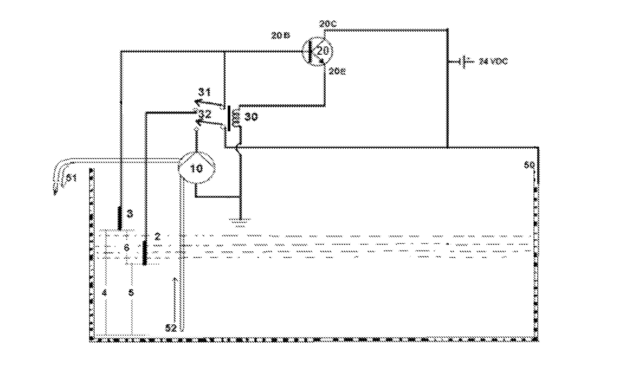
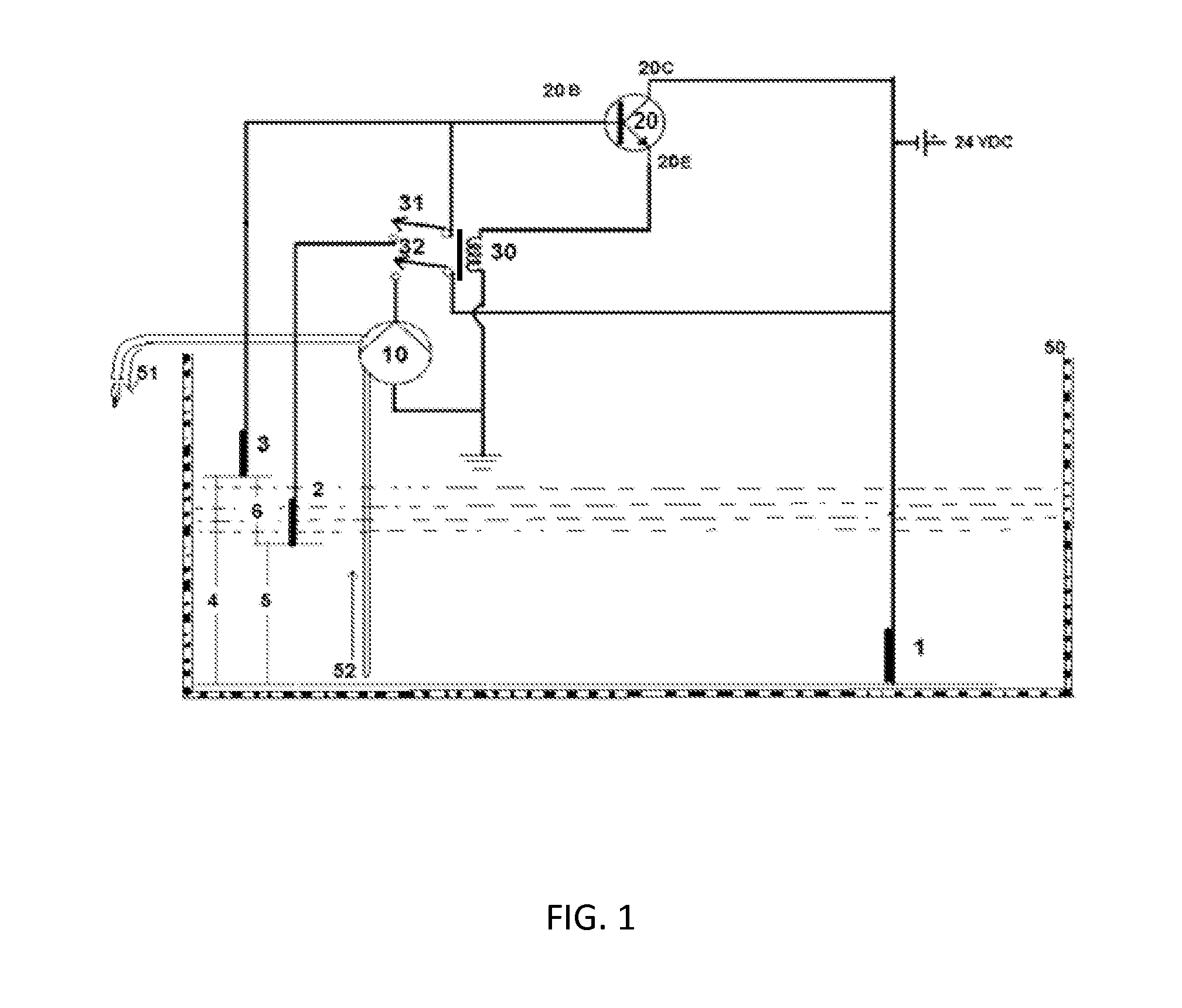
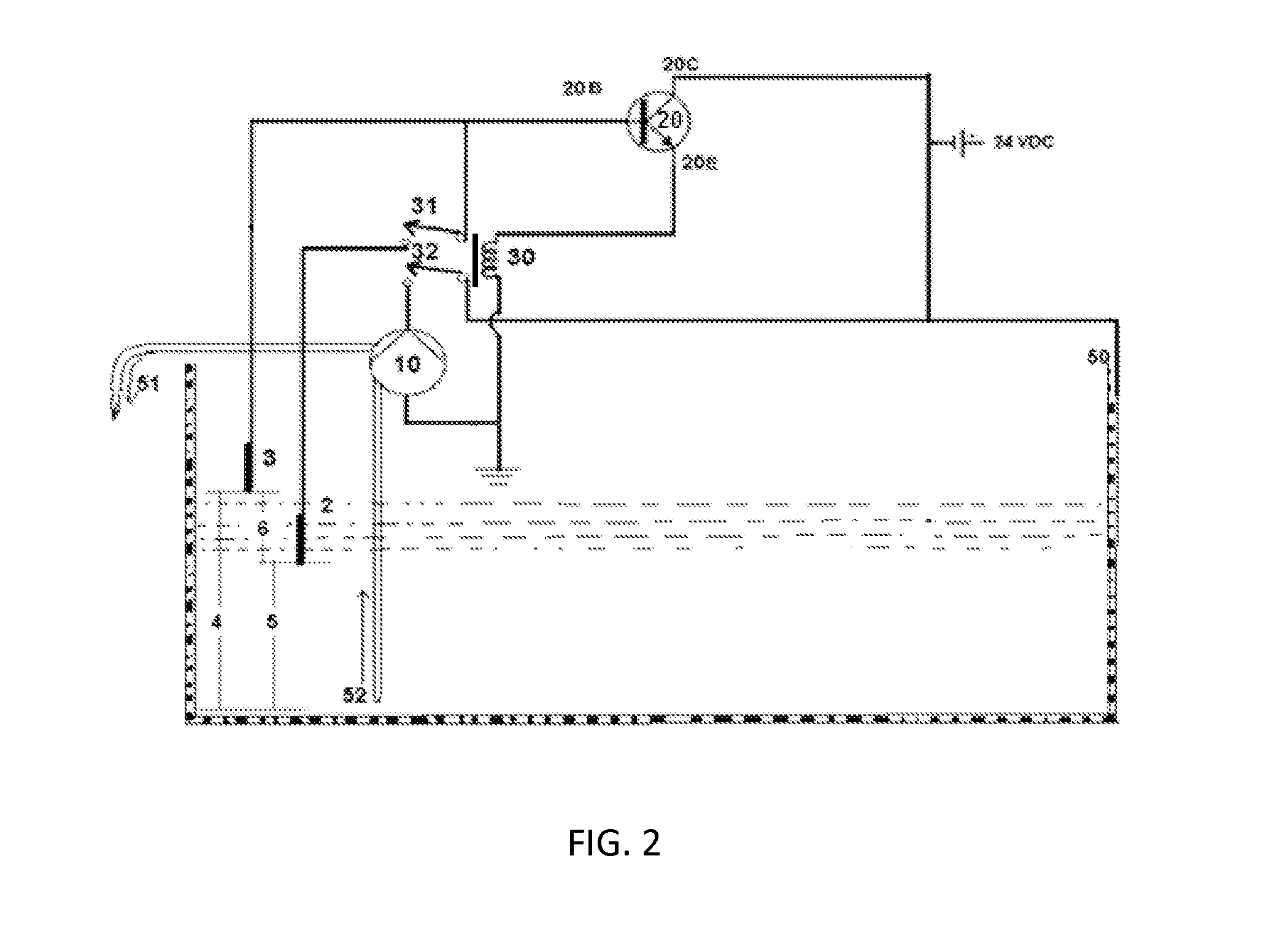
DETAILED DESCRIPTION OF THE DRAWING

[0014]For a better understanding of the nature and objects of the invention, reference should be had to the following detailed description taken in connection with the accompanying drawings, in which: The invention does not use alternating current a / c or high voltage to sense and control the system, does not require a digital processor, does not require float switches, and may be installed in most states by a HVAC (credential) professional without the need of a licensed electrician. Further, the system as presented produces no glow, spark, or flame sufficient to ignite flammable vapors, thereby reducing fire hazards and allowing installation at ground level in States and Municipalities that otherwise would require the system to be kept at a minimum 18 inches off the ground. Applicants system does not present any ignition hazard thereby allowing install in locations not feasible otherwise.

[0015]To improve understanding of the preferred embodiment, w...


PUM


Abstract

A condensate pump system for collecting condensate liquid within a reservoir 50 and pumping out the liquid to predetermined levels comprising a reservoir 50, a, a pump 10, a transistor 20, a relay 30, and a low voltage direct current power source wherein a sensing voltage is introduced (a power probe 1 or reservoir 50) into the condensate liquid such that the liquid level is detected via the two sensing probe conductors (hold probe 2 and on probe 3) within the reservoir 50 transferring the sensing voltage to the base leg 20B of the transistor 20 which in turn powers a relay 30 that powers the pump 10 when the energized liquid is contacting the upper conductor 3 at the desired maximum level 4 and disconnects the pump 10 from power when the energized liquid no longer contacts the lower conductor 2 at the desired minimal level 5.

Description

FIELD OF ART[0001]The inventions relates to system that controls the minimum and maximum liquid levels within a condensate reservoir using only low voltage direct current to energize the liquid, sense the level of the liquid, and power a pump to maintain desired range of liquid level within the reservoirBACKGROUND OF THE INVENTION[0002]Many different methods and apparatus have been deployed for controlling or maintaining predetermined liquid levels within condensate reservoirs using a combination of controller circuits, float switches, pumps and relays. The float switches are prone to failure, especially in the high humidity corrosive environments that condensate pumps often are installed.[0003]One prior art solution taught in U.S. Pat. No. 3,657,556 by Foster addressing marine bilge pump control eliminates the float switches by using two circuits having a plurality of electronic components including several conductors located within the reservoir. The liquid only becomes energized ...

Claims


Application Information

Patent Timeline
IPC IPC(8): G05D9/12
CPCG05D9/12Y10T137/7306
Inventor MCBRIDE, ROSS
Owner MCBRIDE ROSS
Why Eureka
Try Eureka