Swirl impingement prefilming

Inactive Publication Date: 2014-06-12
DELAVAN
View PDF7 Cites 9 Cited by
  • Summary
  • Abstract
  • Description
  • Claims
  • Application Information

AI Technical Summary

Benefits of technology

[0009]The subject invention is directed to a new and useful nozzle for injecting liquid. The nozzle includes a nozzle body defining a plurality of injection point orific

Problems solved by technology

That interaction serves to shear and accelerate the fuel sheet, creating multiple modes o

Method used


Image

  • Swirl impingement prefilming
  • Swirl impingement prefilming
  • Swirl impingement prefilming

Examples


Embodiment Construction

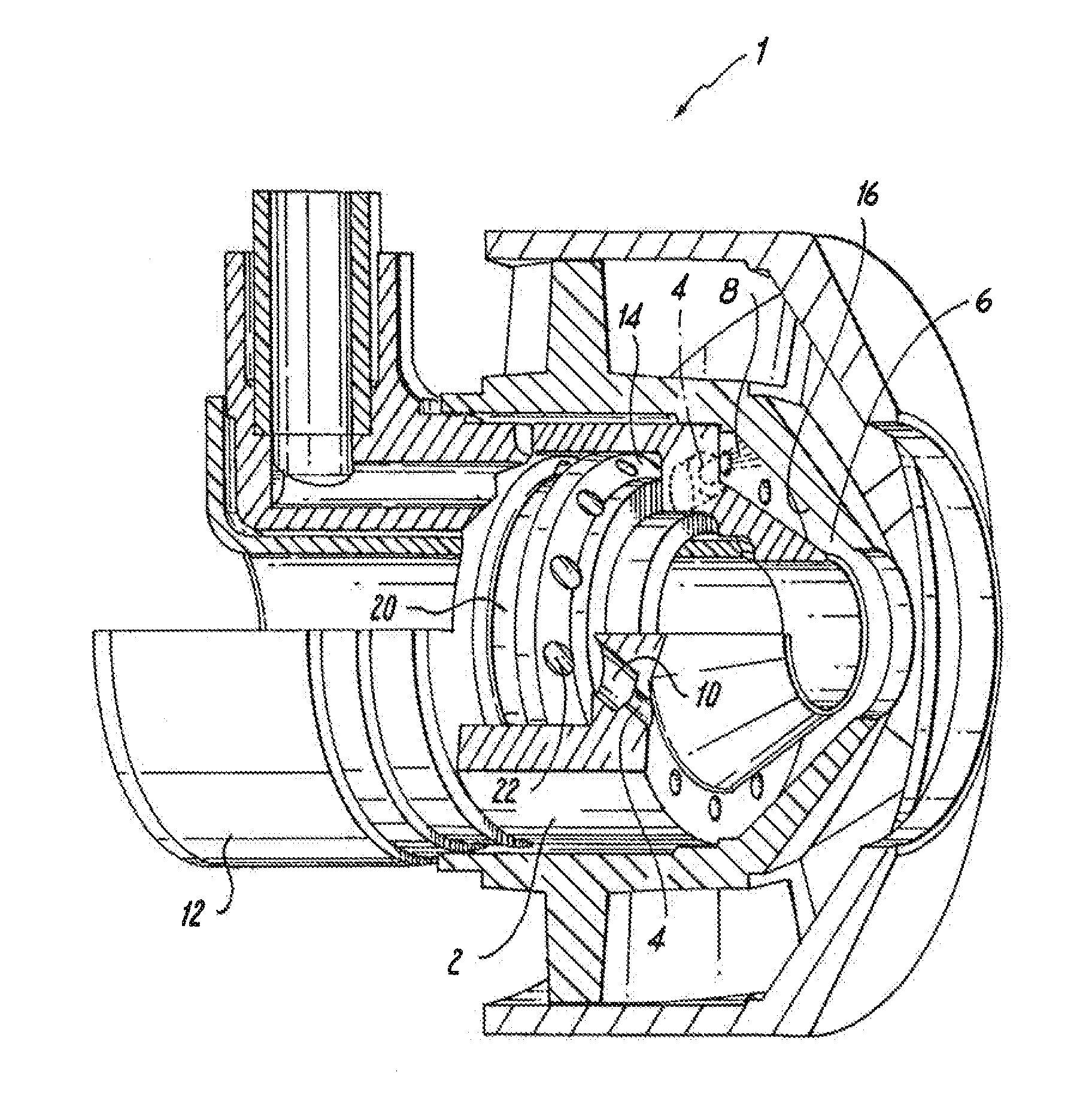
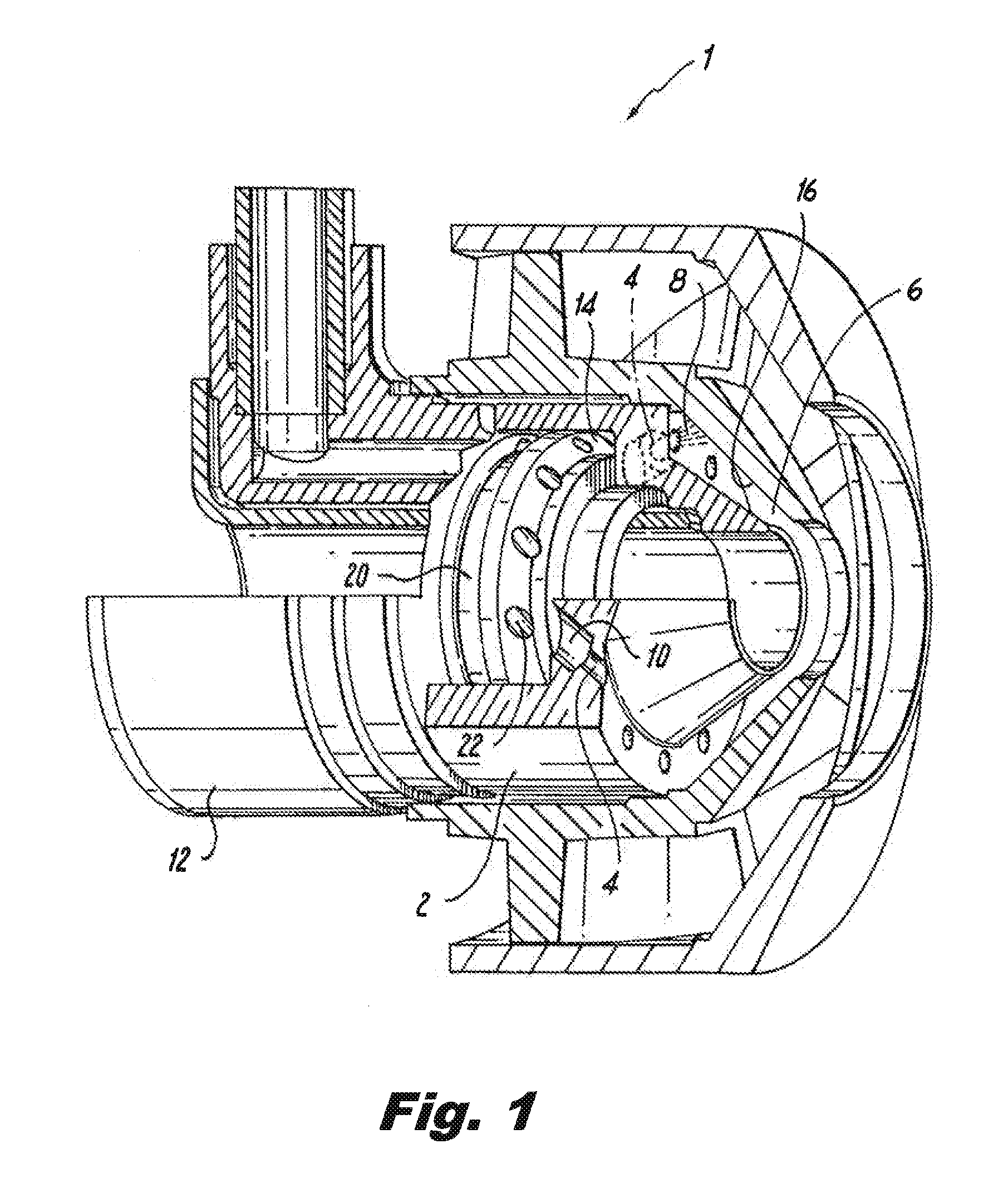
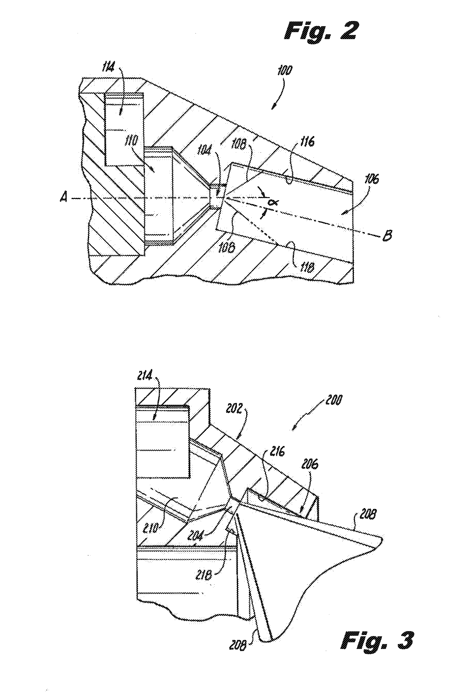
[0020]Reference will now be made to the drawings wherein like reference numerals identify similar structural features or aspects of the subject invention. For purposes of explanation and illustration, and not limitation, a partial view of an exemplary embodiment of a nozzle in accordance with the invention is shown in FIG. 1 and is designated generally by reference character 100. Other embodiments of nozzles in accordance with the invention, or aspects thereof, are provided in FIGS. 2-5, as will be described. The systems and methods of the invention can be used to improve filming characteristics, discharge coefficients, hydraulic cone angles, and the like.

[0021]Referring now to FIG. 1, nozzle 1 includes a nozzle body 2 defining a plurality of injection point orifices 4, and a prefilmer 6 positioned downstream of injection point orifices 4 for impingement of spray on prefilmer 6. Injection point orifices 4 are oriented such that spray cones 8 issuing from orifices 4 impinge on prefil...


PUM


Abstract

A nozzle for injecting liquid includes a nozzle body defining a plurality of injection point orifices and an annular prefilmer positioned downstream of the injection point orifices for prefilming impingement of spray from the injection point orifices on the prefilmer. A swirl antechamber can be defined upstream of the injection point orifices for supplying a swirling liquid flow to the injection point orifices for impingement of a swirling flow on the prefilmer.

Description

CROSS-REFERENCE TO RELATED APPLICATIONS[0001]This application claims the benefit of priority to U.S. Provisional Patent Application No. No. 61 / 809,582 filed Apr. 8, 2013, and is a Continuation-in-part of U.S. patent application Ser. No. 13 / 767,402 filed Feb. 14, 2013, which claims the benefit of priority to U.S. Provisional Patent Application No. 61 / 599,659 filed Feb. 16, 2012, each of which is incorporated by reference herein in its entirety.BACKGROUND OF THE INVENTION[0002]1. Field of the Invention[0003]The present invention relates to liquid injection and atomization, and more particularly to multi-point fuel injection such as in gas turbine engines.[0004]2. Description of Related Art[0005]A variety of devices are known for injecting or spraying liquids, and for atomizing liquids into sprays of fine droplets, such as for gas turbine engines. Pre-filming air-blast fuel injector nozzles for issuing atomized fuel into the combustor of a gas turbine engine are well known in the art. ...

Claims


Application Information

Patent Timeline
IPC IPC(8): F02M61/16
CPCF23R3/28F23D11/383F23D2213/00F23D2900/11101F23D11/38F23D2900/11001F02M61/162
Inventor BUELOW, PHILIP E.O.RYON, JASON A.SHORT, JOHN E.
Owner DELAVAN
Why Eureka
Try Eureka