Wireless Power System

Active Publication Date: 2014-06-12
WIPQTUS
View PDF4 Cites 28 Cited by
  • Summary
  • Abstract
  • Description
  • Claims
  • Application Information

AI Technical Summary

Benefits of technology

[0006]The wireless power system and method disclosed herein enables the delivery of a safe amount of power from a higher rated power wireless power transmitter to a lower rated power wireless power receiver. The wireless power system and method disclosed herein constrains the wireless power transmitter to transmit a known level of maximum power through multitude of techniques comprising, f

Problems solved by technology

However, the clamping mechanisms can drain away only up to a certain amount of excess power.
This power limit of the clamping mechanism is set at the time of designing the clamping mechanism.
When the excess power during the actual operation exceeds this power limit, the clamping mechanism will be damaged and will not be able to protect the main circuitry of the wireless power receiver any further.
In that situation, the m

Method used


Image

  • Wireless Power System
  • Wireless Power System
  • Wireless Power System

Examples


Embodiment Construction

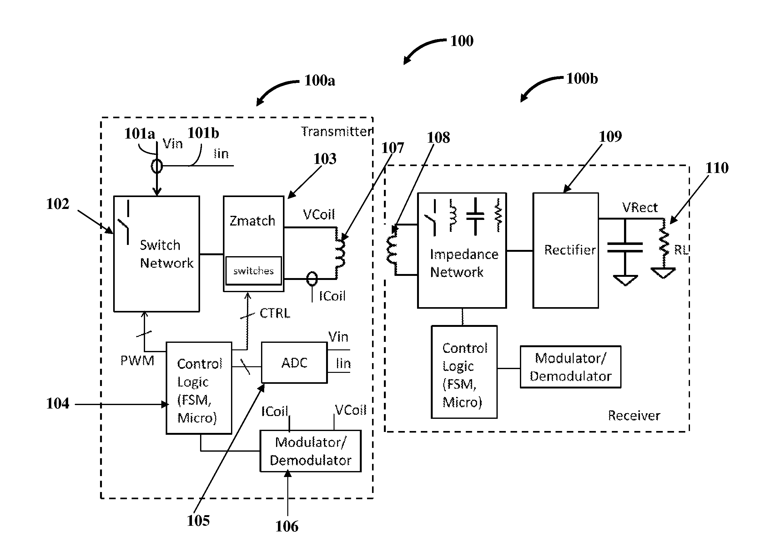
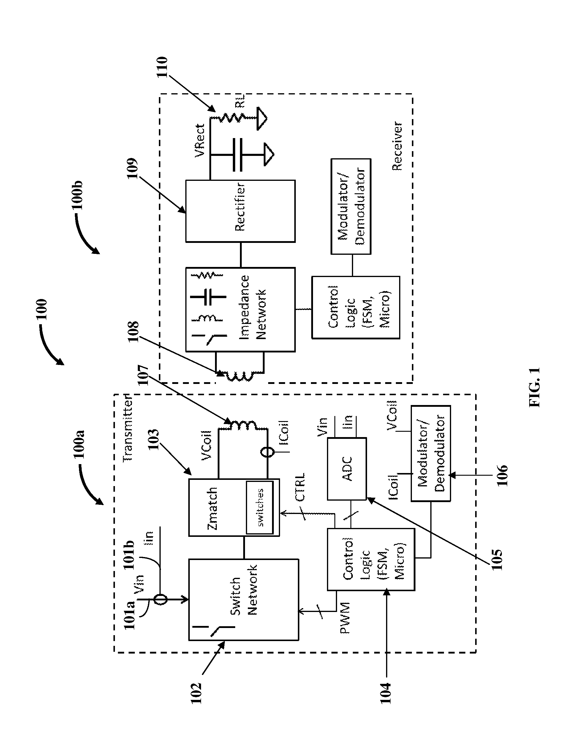
[0019]FIG. 1 exemplarily illustrates a schematic diagram of a wireless power system 100 comprising a higher rated power wireless power transmitter 100a that provides power to a lower rated power wireless power receiver 100b, without exceeding the rated power of the wireless power receiver 100b. In an embodiment, the wireless power system 100 disclosed herein is configured as an inductive wireless power transfer system. The inductive wireless power transfer system comprises a wireless power transmitter 100a that generates an electromagnetic field to a coupling region for providing energy transfer to the wireless power receiver 100b. The wireless power transmitter 100a disclosed herein reconfigures itself to transmit a safe known amount of power sufficient for the wireless power receiver 100b to deliver its rated power to its load. By constraining its maximum power transmitted, the higher power wireless power transmitter 100a protects and safeguards the lower power wireless power rece...


PUM


Abstract

A higher power wireless power transmitter (HPWPT) including a first, second and third circuit and a transmit coil for wirelessly powering a lower power wireless power receiver (LPWPR) is provided. The first circuit is a switch network. The second circuit is variable impedance network and/or a tuning network. The third circuit is a control logic circuit configured to change the input voltage source or topology of the first circuit, to change the impedance and/or tuning characteristics of the second circuit, to select the transmit coil, vary frequency or duty cycle of the PWM signal or any combination thereof. The change in the input voltage or topology of first circuit or change in impedance or tuning characteristics of second circuit or change in the transmit coil used or the applied constraints on the frequency and duty cycle of the PWM signal constrain the maximum power transmitted by the HPWPT to LPWPR.

Description

CROSS REFERENCE TO RELATED APPLICATIONS[0001]This application claims the benefit of provisional patent application No. 61 / 672,784 titled “Wireless Power Charging System”, filed in the United States Patent and Trademark Office on Jul. 18, 2012.[0002]The specification of the above referenced patent application is incorporated herein by reference in its entirety.BACKGROUND[0003]A low power wireless power receiver, for example, rated at 5 Watts (W), when receiving power from a higher power wireless power transmitter, for example, rated at 65 W needs to be protected against excessive power potentially being transmitted from the wireless power transmitter. Conventional wireless power receivers typically have a clamping mechanism to guard against harmful voltage and current conditions which occur when excessive power is received. These clamping mechanisms divert the excess power away from the main circuitry of the wireless power receiver thereby protecting the main circuitry of the wireles...

Claims


Application Information

Patent Timeline
IPC IPC(8): H01F38/14
CPCH02J50/10H02J50/12
Inventor SANKAR, GANAPATHYSINGH, MANJIT
Owner WIPQTUS
Why Eureka
Try Eureka