Method for printing contiguous swaths

a contiguous swath and printing technology, applied in printing, other printing apparatus, etc., can solve the problem of not being able to change the relation between the print element and the image line, and achieve the effect of shortening the processing time for defining and applying the digital mask and being significan

Active Publication Date: 2014-06-12
OCE TECH
View PDF2 Cites 1 Cited by
  • Summary
  • Abstract
  • Description
  • Claims
  • Application Information

AI Technical Summary

Benefits of technology

[0012]In the step of preparing first swath image data, the image is processed in such a way that every print element is associated with an image line in the image. This is usually done during the time a previous swath is printed, because of the significant processing time that is needed. In the processing, the position of the print elements is considered, so, in general, it is not possible to change the relation between the print element and the image line within a short time frame. An advancement step, or paper step, is defined in dependence on the print mode and printed first swath. After applying this paper step, the print head overlaps the first swath in order to have in a second swath a number of print elements associated with image lines that were also associated with other print elements in the first swath. In dependence on a determined relative position of the printed first swath and a current position of the print head, a digital mask that prevents the application of print elements that would apply marking material on positions where already sufficient marking material has been printed, can be defined and applied without extensive calculations. Thus, no dark line appears at the boundary of the swaths. The overlap of the print head also gives the possibility to print some extra image lines, if the distance between the two swaths is too large to completely cover the image receiving material with marking material. In that case the digital mask is defined to prevent the application of a smaller number of print elements. Thus, no light line appears at the boundary of the swaths. Since the processing time for defining and applying a digital mask can be made very short, it is possible to determine the edge of the first swath in dependence on the position of the print head in the scanning direction. In this way, the second swath can be made to follow the edge of the first swath and the two neighbouring swaths can be made to join each other without dark or light line between them. A further advantage is that the side of the second swath that does not adjoin the first swath is unaffected by the application of the digital mask. Therefore, there is no way that irregularities in the edge of the first swath propagate to an edge of the second swath, except where it is necessary to make the edges of the swaths adjoin.
[0013]In a further embodiment, the advancement step is based on a measurement of a distance between two swaths. This has the advantage that media for which no calibration of the relation between the rotation and the lateral displacement has taken place, will have a paper step size that is nominally adjusted to the swath width.
[0015]In a further embodiment, the determined position of the first swath is used to adapt a position of a digital mask that is applied for interweaving the first and second swath. This has an additional advantage in that, when a pixel in an image line disappears due to an overlap between the two swaths, a next pixel may be from a different image line and it is not possible that a complete image line remains unprinted.

Problems solved by technology

In the processing, the position of the print elements is considered, so, in general, it is not possible to change the relation between the print element and the image line within a short time frame.

Method used


Image

  • Method for printing contiguous swaths
  • Method for printing contiguous swaths
  • Method for printing contiguous swaths

Examples


Embodiment Construction

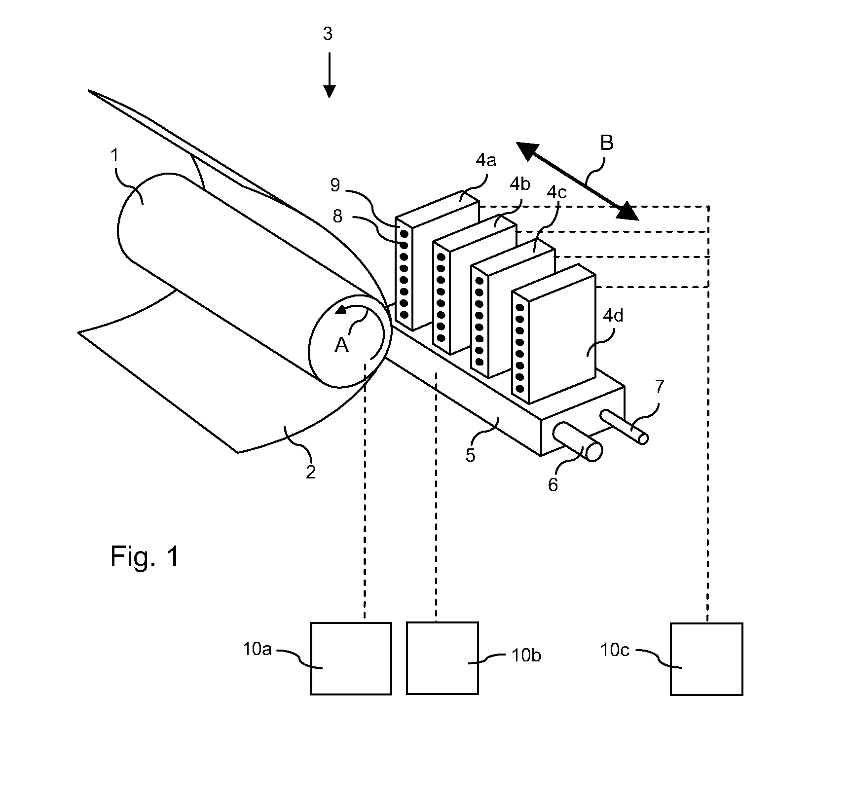
[0030]FIG. 1 shows an ink jet printing assembly 3 that may be applied for the invented method. The ink jet printing assembly 3 comprises supporting means for supporting an image receiving member 2. The supporting means are shown in FIG. 1 as a platen 1, but alternatively, the supporting means may be a flat surface. The platen 1, as depicted in FIG. 1, is a drum, which is rotatable about its axis as indicated by arrow A. The supporting means may be optionally provided with suction holes for holding the image receiving member in a fixed position with respect to the supporting means. The ink jet printing assembly 3 comprises print heads 4a-4d, mounted on a scanning print carriage 5. The scanning print carriage 5 is guided by suitable guiding means 6, 7 to move in reciprocation in the main scanning direction B. Each print head 4a-4d comprises an orifice surface 9, which orifice surface 9 is provided with at least one orifice 8. The print heads 4a-4d are configured to eject droplets of m...


PUM


Abstract

A method for printing an image on an image receiving member is provided, in which a print head having an array of print elements moves in a scanning direction to print image lines and the image receiving member is advanced in a transport direction after printing a swath. In order to obtain various contiguous swaths of print lines without a light or dark line between the swaths, the position of a prior swath printed preceding to a current swath is determined during the printing of the current swath. A digital mask is applied to the print data that is associated with the print elements at the to the prior swath adjoining edge of the current swath in dependence on the determination of the position of the prior swath.

Description

FIELD OF THE INVENTION[0001]The invention relates to a method for printing an image on an image receiving member in a plurality of swaths, each swath being printed by a print head that reciprocates in a scanning direction, the print head being configured to apply marking material to the image receiving material in accordance with image data provided to the print head and the image receiving member being advanced stepwise in a transport direction, which is substantially perpendicular to the scanning direction. The invention further relates to a print system, configured to perform said method.BACKGROUND OF THE INVENTION[0002]Print processes that employ a print head for printing swaths comprising a number of image lines in a direction perpendicular to a transport direction of an image receiving member, such as, for example, a paper sheet or paper supplied from a roll, rely on an accurate transport of the image receiving member or the print head in order to have different swaths correct...

Claims


Application Information

Patent Timeline
Patent Type & Authority Applications(United States)
IPC IPC(8): B41J2/07
CPCB41J2/07B41J2/2132B41J11/46
Inventor KLEIN KOERKAMP, KOEN JOANDE GRIJS, EDUARD T. H.SEVERT, ROBERT W.M.KUIPER, PAUL
Owner OCE TECH
Why Eureka
Try Eureka