Eureka AIR delivers breakthrough ideas for toughest innovation challenges, trusted by R&D personnel around the world.

Surgical microscope

a microscope and surgical technology, applied in the field of surgical microscopes, can solve the problems of inability to accurately and permanently adjust, inability to move and vibrate the microscope, and the majority of cases are stiff, so as to achieve the effect of reducing interruption periods

Inactive Publication Date: 2014-06-12
LEICA MICROSYSTEMS (SCHWEIZ) AG
View PDF3 Cites 0 Cited by
  • Summary
  • Abstract
  • Description
  • Claims
  • Application Information

AI Technical Summary

Benefits of technology

The present invention aims to minimize interruptions caused by movements of a surgical microscope due to manual adjustments of observer tubes. The invention achieves this by effectively avoiding movements and vibrations of the microscope resulting from adjusting the position or orientation of observer tubes. This results in a surgical microscope that can be used again after an adjustment faster than conventional approaches. The invention offers a positioning and / or orientation device that can be used for both the principal surgeon and the assistant, ensuring quick and efficient adjustment of the microscope's orientation. Additionally, the device allows for the position and orientation existing before a movement of the surgical microscope to be re-established, making it useful in cases of relatively small changes in microscope position. Furthermore, the device is designed to be manually adjustable for safety concerns, ensuring safe operation even in case of a defect in the electronic or electronically activated components of the orientation and positioning device.

Problems solved by technology

It is regarded as a particular disadvantage of conventional slip couplings that they are in most cases stiff, and must be very accurately and permanently adjusted for proper operation.
Manual adjustment of the tubes in this manner also results in undesired movements and vibrations of the microscope, thereby extending, for example, the interruption periods between two desired positions of the surgical microscope, during which observation is not possible.
This can result in delays in performing a procedure.
In particular, the need to adjust the co-observer's tube after a repositioning of the surgical microscope results in time delays during which the principal surgeon cannot work.

Method used


Image

  • Surgical microscope
  • Surgical microscope

Examples


Embodiment Construction

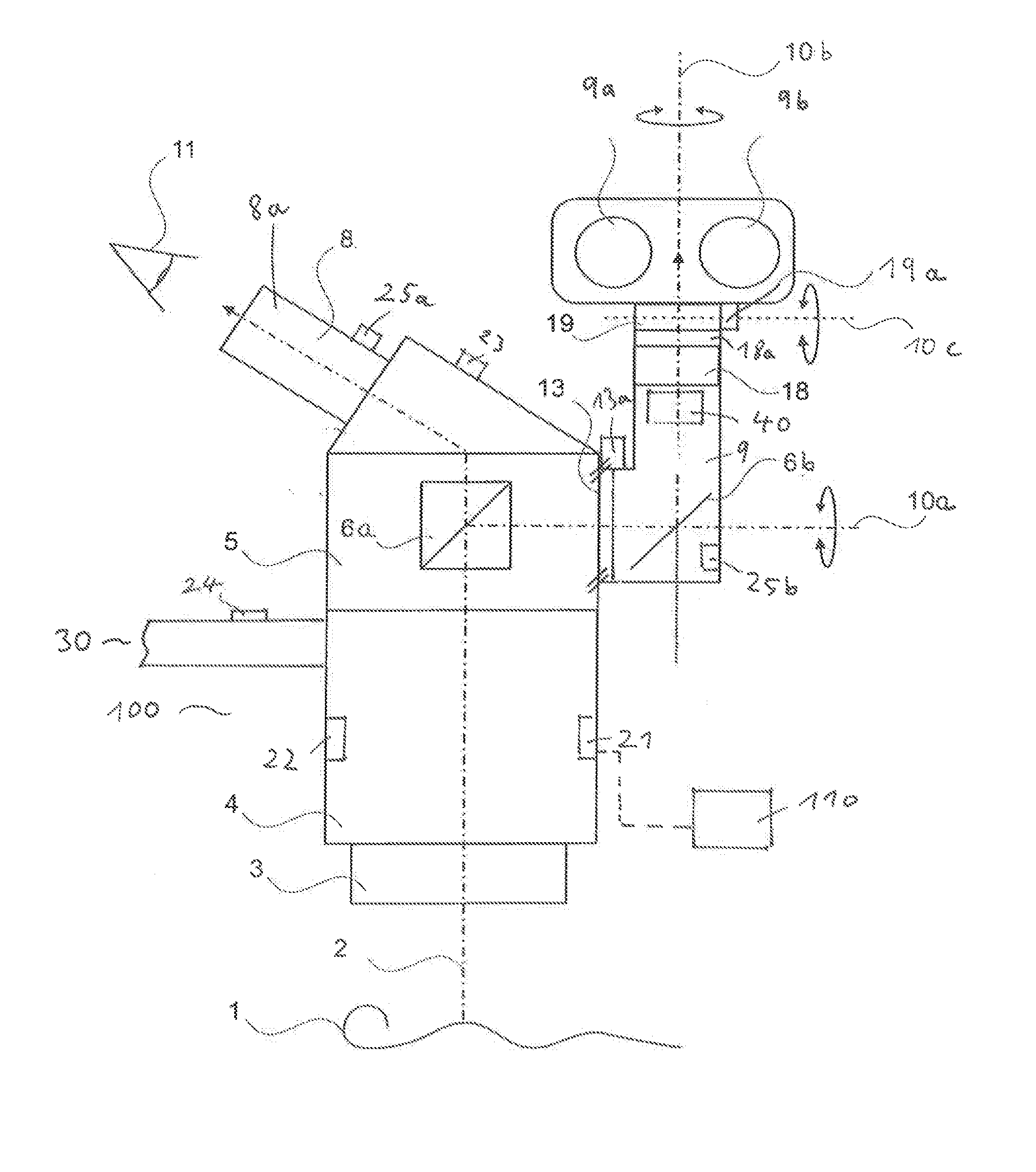
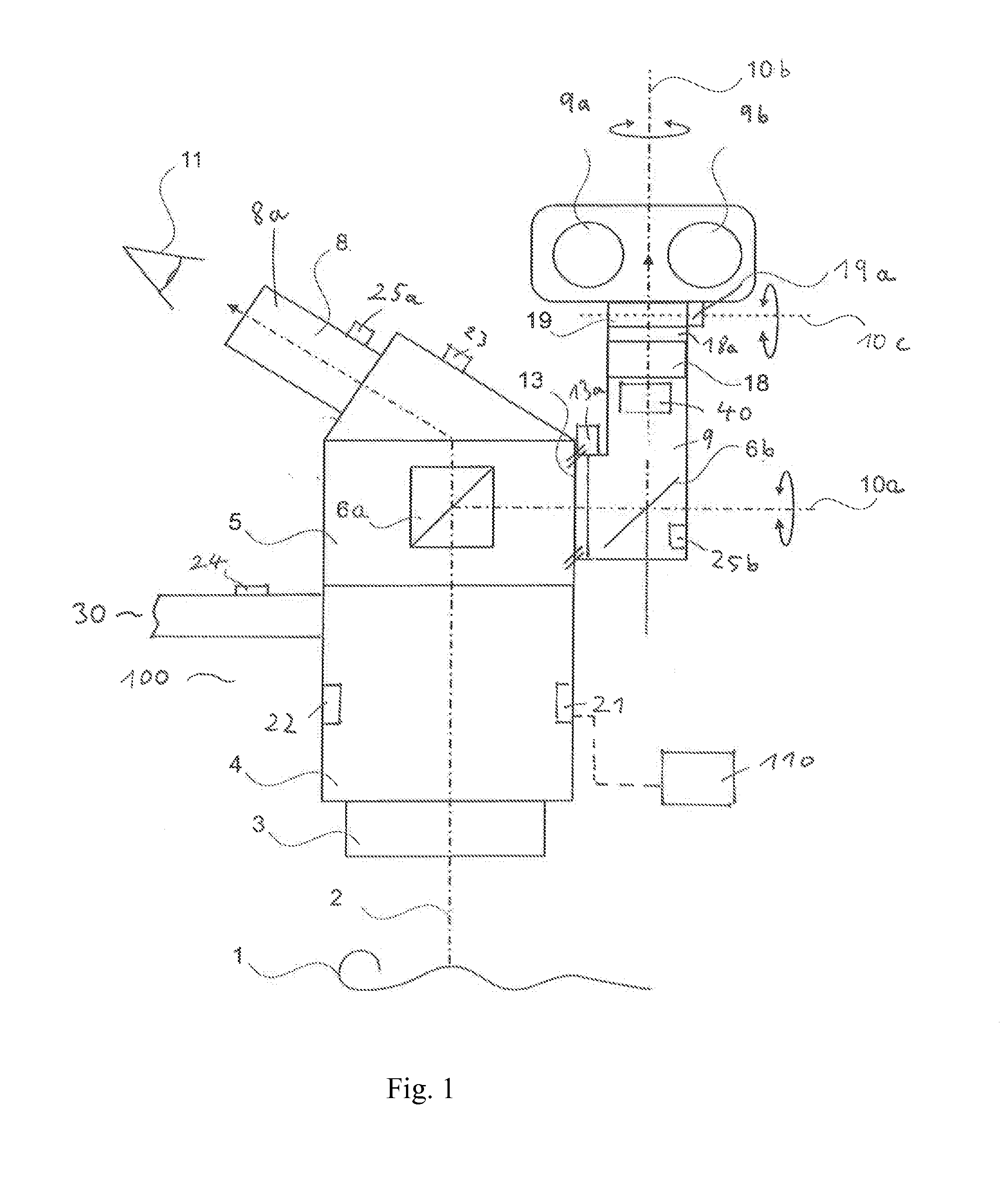
[0025]In FIG. 1, a preferred embodiment of a surgical microscope according to the present invention is depicted in a side view and is labeled 100 in its entirety. Surgical microscope 100 is embodied with a housing 5. In the side view depicted, only the right main stereo beam path 2 for the right eye 11 of a surgeon (principal surgeon) is depicted. Deflection elements and components for separating a beam path for the principal surgeon and for an assistant are labeled 6a, 6b.

[0026]The surgical microscope comprises a first tube 8 for the principal surgeon and a second tube 9 for the assistant. Both tubes 8, 9 are provided as binocular tubes; for perspective reasons, the depiction in FIG. 1 shows one eyepiece 8a for tube 8 and two eyepieces 9a, 9b for tube 9.

[0027]To ensure optimum observation of an object 1, surgical microscope 100 is pivotable through various angles in all three spatial dimensions in order to provide desired or suitable view angles onto object 1. In FIG. 1 this viewi...


PUM


Abstract

The present invention relates to a surgical microscope comprising a first tube (8) and a second tube (9), wherein at least one sensor (21, 22, 23, 24, 25a, 25b) for sensing the position and / or orientation of the surgical microscope in three dimensions is provided, the first tube (8) and / or the second tube (9) being provided with a positioning and / or orientation device (110, 13, 18, 19, 13a, 18a, 19a) for positioning and / or orienting the first and / or the second tube (8, 9) as a function of a position and / or orientation, sensed by means of the at least one sensor (21, 22, 23, 24, 25a, 25b), of the surgical microscope in space.

Description

CROSS REFERENCE TO RELATED APPLICATIONS[0001]This application claims priority of German patent application number 10 2012 222 578.1 filed Dec. 7, 2012, the entire disclosure of which is incorporated by reference herein.FIELD OF THE INVENTION[0002]The present invention relates to a surgical microscope having a first microscope tube and a second microscope tube.BACKGROUND OF THE INVENTION[0003]Surgical microscopes embodied as stereomicroscopes generally comprise a first stereoscopic tube for a principal surgeon and a second tube for a co-observer or assistant. This second tube is usually stereoscopic, but can also be embodied monoscopically. Surgical microscopes of this kind are known, and are usable in particular in ophthalmic and neurosurgical procedures.[0004]During a procedure, a surgical microscope is often adjusted in three dimensions in terms of its position and / or orientation.[0005]An adjustment of this kind is carried out as a rule by the principal surgeon, with the result th...

Claims


Application Information

Patent Timeline
IPC IPC(8): G02B21/18G02B21/00
CPCG02B21/18G02B21/0012G02B21/22G02B21/26
Inventor SANDER, ULRICH
Owner LEICA MICROSYSTEMS (SCHWEIZ) AG
Why Eureka
Eureka Blog
Learn More