Control circuit for multi-phase, multi-channels pfc converter with variable switching frequency

Active Publication Date: 2009-04-09
SEMICON COMPONENTS IND LLC
View PDF12 Cites 12 Cited by
  • Summary
  • Abstract
  • Description
  • Claims
  • Application Information

AI Technical Summary

Benefits of technology

[0006]An exemplary embodiment of the invention provides a switching control circuit for multi-phases and multi-channels PFC converter. It includes a PFC-control circuit coupled to a first inductor and the output of the PFC converter to receive a first-inductor signal and a feedback signal for generating a first-switching signal. The first-switching signal is utilized to switch the first inductor for power factor correction. A phase-detection circuit detects the first-switching signal and a second-inductor signal for generating a start signal and a phase-lock signal. The start signal is generated in accordance with the switching period of the first-switching signal. The start signal is coupled to enable a second-switching signal. The second-switching signal is applied to switch a second inductor. An on-time-adjust circuit is developed to adjust the on time of the second-switching signal in accordance with the phase-lock signal. The on

Problems solved by technology

The high current demand normally decreases

Method used


Image

  • Control circuit for multi-phase, multi-channels pfc converter with variable switching frequency
  • Control circuit for multi-phase, multi-channels pfc converter with variable switching frequency
  • Control circuit for multi-phase, multi-channels pfc converter with variable switching frequency

Examples


Example

[0023]The following description is of the best-contemplated mode of carrying out the invention. This description is made for the purpose of illustrating the general principles of the invention and should not be taken in a limiting sense. The scope of the invention is best determined by reference to the appended claims.

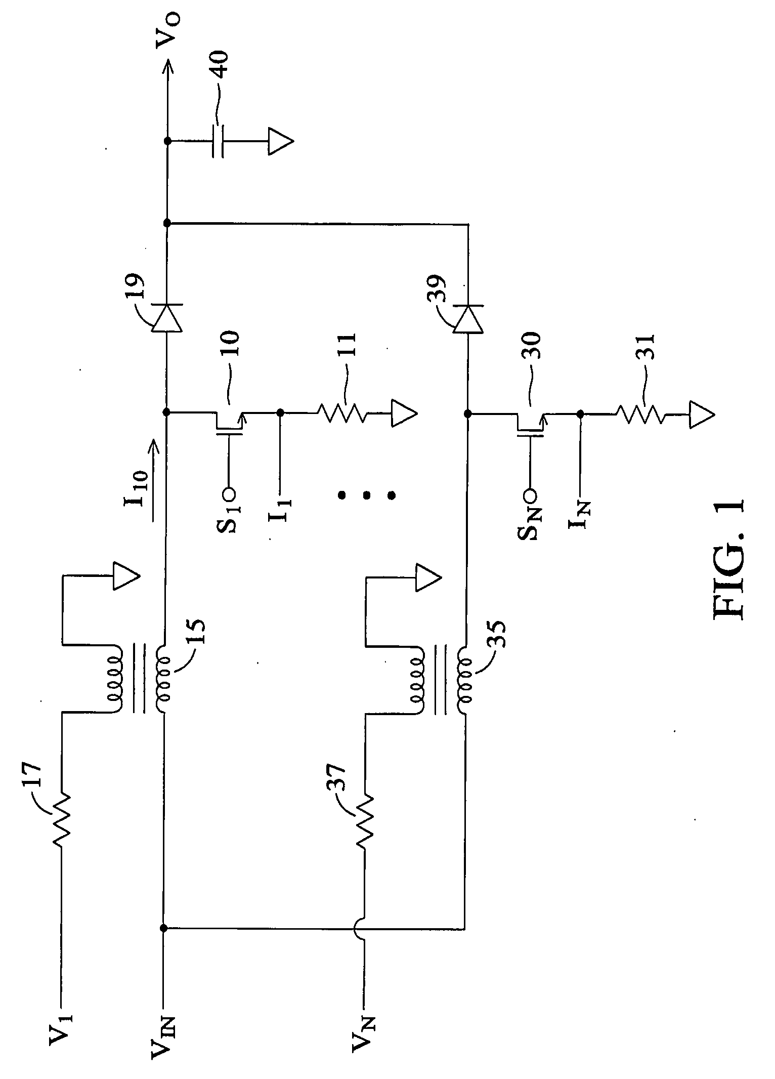
[0024]FIG. 1 shows a preferred embodiment of parallel PFC converters according to the present invention. A transistor 10, an inductor 15 and a rectifier 19 develop a first power converter. A first-switching signal S1 is coupled to control the transistor 10 for switching the inductor 15. The rectifier 19 and a capacitor 40 are utilized to generate the output voltage VO of the PFC converter. Another transistor 30, an inductor 35 and a rectifier 39 develop another power converter coupled to the output voltage VO. A second-switching signal SN is coupled to control the transistor 30 for switching the inductor 35. The outputs of power converters are parallel connected. The i...


PUM


Abstract

A switching control circuit for multi-phases PFC converters is provided. It includes a PFC-control circuit coupled to receive a first-inductor signal and a feedback signal for generating a first-switching signal. The first-switching signal is utilized to switch the first inductor for power factor correction. A phase-detection circuit detects the first-switching signal and a second-inductor signal for generating a start signal and a phase-lock signal. The start signal is developed to enable a second-switching signal. The second-switching signal is coupled to switch a second inductor. An on-time-adjust circuit is coupled to adjust the on time of the second-switching signal in accordance with the phase-lock signal. The phase-lock signal is correlated to the period between the end of the second-inductor signal and the start of the second-switching signal.

Description

BACKGROUND OF THE INVENTION[0001]1. Field of the Invention[0002]The invention relates to a switching power converter, and more particularly to a control circuit of power factor correction (PFC) converters.[0003]2. Description of the Related Art[0004]The high current demand normally decreases the power efficiency in the power converter. The power loss of the power converter is exponentially proportional to its current.PLOSS=I2×R   (1)where I is the switching current of the power converter, R is the impedance of the switching devices such as the equivalent resistance of the inductor and the transistor, etc.[0005]Therefore, parallel technologies are developed for reducing the power consumption of power converter. The PFC (power factor correction) power converter is utilized to improve the power factor of AC power source. The detail skill of the PFC circuit can be found in prior arts, such as U.S. Pat. No. 7,116,090 “Switching control circuit for discontinuous mode PFC converters”. The ...

Claims


Application Information

Patent Timeline
IPC IPC(8): G05F1/00
CPCH02M1/4225Y02B70/126H02M2003/1586H02M3/1584Y02B70/10Y02P80/10H02M3/1586
Inventor YANG, TA-YUNG
Owner SEMICON COMPONENTS IND LLC
Why Eureka
Try Eureka