X-ray analyser

a technology of x-ray analyzer and x-ray detector, which is applied in the field of x-ray analyzer, can solve the problems of x-ray detector experiencing a very high overload condition, the lens field may not be strong enough, and the number of high-energy x-rays and backscattered electrons is huge, so as to minimise the potential damage of the silicon drift detector and the disturbance of the operation of the microscope.

Inactive Publication Date: 2012-11-01
OXFORD INSTR NANOTECH TOOLS
View PDF6 Cites 13 Cited by
  • Summary
  • Abstract
  • Description
  • Claims
  • Application Information

AI Technical Summary

Benefits of technology

[0023]To reduce mechanical vibration of the microscope during retraction, the use of a heavy liquid nitrogen-based cooling system (which typically comprises a dewar containing liquid nitrogen) is avoided. This is made possible by the use of a silicon drift detector. A silicon drift detector is advantageous since it provides excellent detection performance, can be cooled effectively using Peltier cooling and is also lightweight. A suitable Peltier cooling system may take a number of configurations. However, preferably a Peltier stack is provided in thermal contact with the detector and a heat pipe is provided to remove the heat from the detector to a distal location.
[0026]Thus, the surrounding end portion of the housing is formed from a lightweight, very low magnetic permeability material with good strength and x-ray absorption capability. The relative magnetic permeability of the material is less than 1.004, more preferably less than 1.002, even more preferably less than 1.001 and most preferably less than 1.0001. Typically the material of the end portion is a metal having a largest constituent by weight selected from the group of: titanium, copper, molybdenum. Thus the material may be a pure metal such as titanium or molybdenum or an alloy such as titanium-aluminium or phosphor bronze.
[0027]The use of lightweight materials is advantageous in that it provides the ability to move the analyser from the analysis to the retracted position very rapidly without the need for a large and powerful carriage mechanism and motor. With the analyser according to the invention, the analyser may be moved from the analysis position to the retracted position within a few seconds. The advantage of this rapid movement is that it minimises the potential damage to the silicon drift detector. A further advantage is that the period of disturbance to the operation of the microscope is also minimised.
[0028]The analyser preferably further comprises an outer tubular housing having a bore through which at least the end portion may pass upon moving between the analysis and retracted positions. Typically this outer tubular housing is sealed to the microscope when in use and the end portion and detector are passed through the outer tubular housing to be inserted into the analysis position within the microscope chamber. Optionally the outer tubular housing may be provided with a flap which is adapted to be moved to an open position when the silicon drift detector is in the analysis position and to be moved to a closed position, thereby closing off the bore, when the silicon drift detector is in the retracted position. Such a flap provides additional protection of the silicon drift detector when it is withdrawn to the retracted position (beyond the flap) and also reduces the possibility of high energy particles from escaping the microscope chamber.

Problems solved by technology

Under low magnification conditions the lens field may not be strong enough to direct the backscattered electrons up inside the pole piece and some high energy backscattered electrons may travel towards the x-ray sensor.
Furthermore, the specimen is usually mounted on a metal support grid and if the specimen is moved so that the incident beam falls on a thick grid bar, there will be a huge increase in the numbers of high energy x-rays and backscattered electrons generated.
Therefore, when the operator is examining a specimen and moving either the specimen or the incident beam position, there may be conditions where the x-ray detector experiences a very high overload condition.
Lowe points out an undesirable effect of autoretraction when using a detector cooled by liquid nitrogen (LN2) because the LN2 dewar is heavy and the retraction movement can cause substantial vibration of the column.
Lowe also points out that any magnetic materials (for example some tungsten and all nickel alloys) in close proximity to the beam can cause astigmatism and shift.
Aluminium is a reasonable choice for a non-magnetic material but is not very strong and is not a good absorber for x-rays.
In practice, despite the precautions taken by the use of non-magnetic materials, the TEM image may still shift when the detector moves in or out.
However, if the detector is moved automatically in response to some signal and the movement is not initiated directly by the operator, the operator may suddenly see an unexpected shift of the image.
If the magnitude of the unexpected shift of the image is larger than the field of view, then the operator will lose any reference to anything in the field of view and will have to search again to locate the feature of interest.

Method used


Image

  • X-ray analyser
  • X-ray analyser

Examples


Embodiment Construction

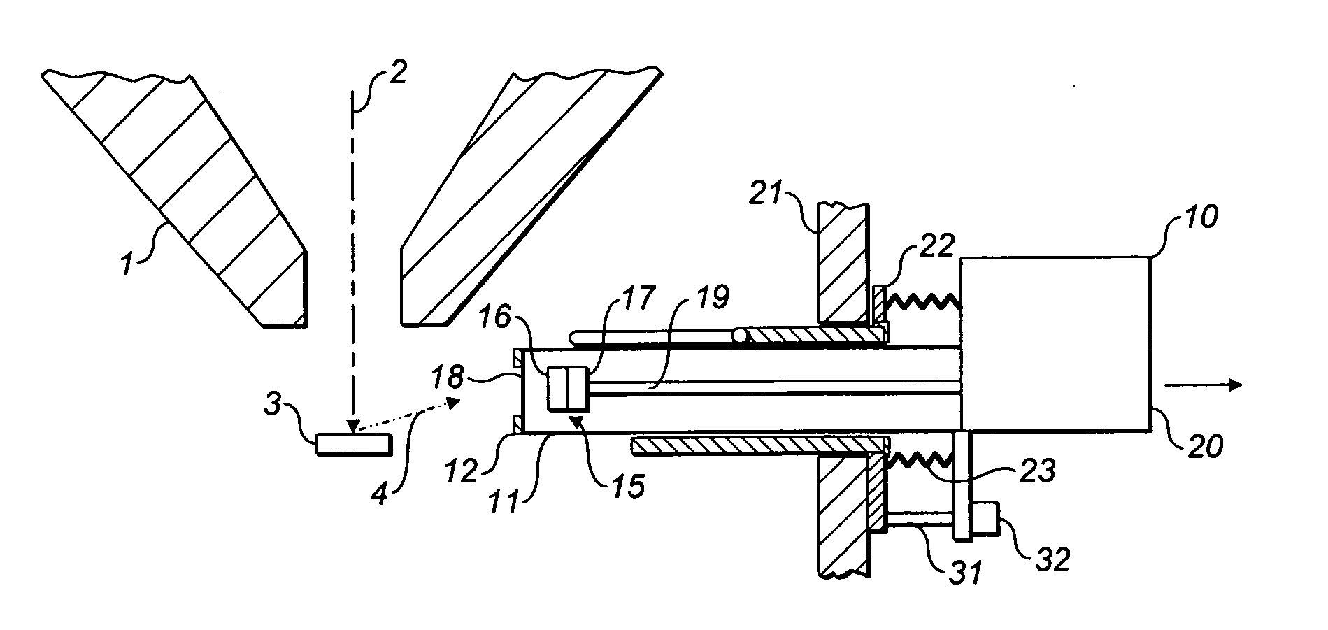
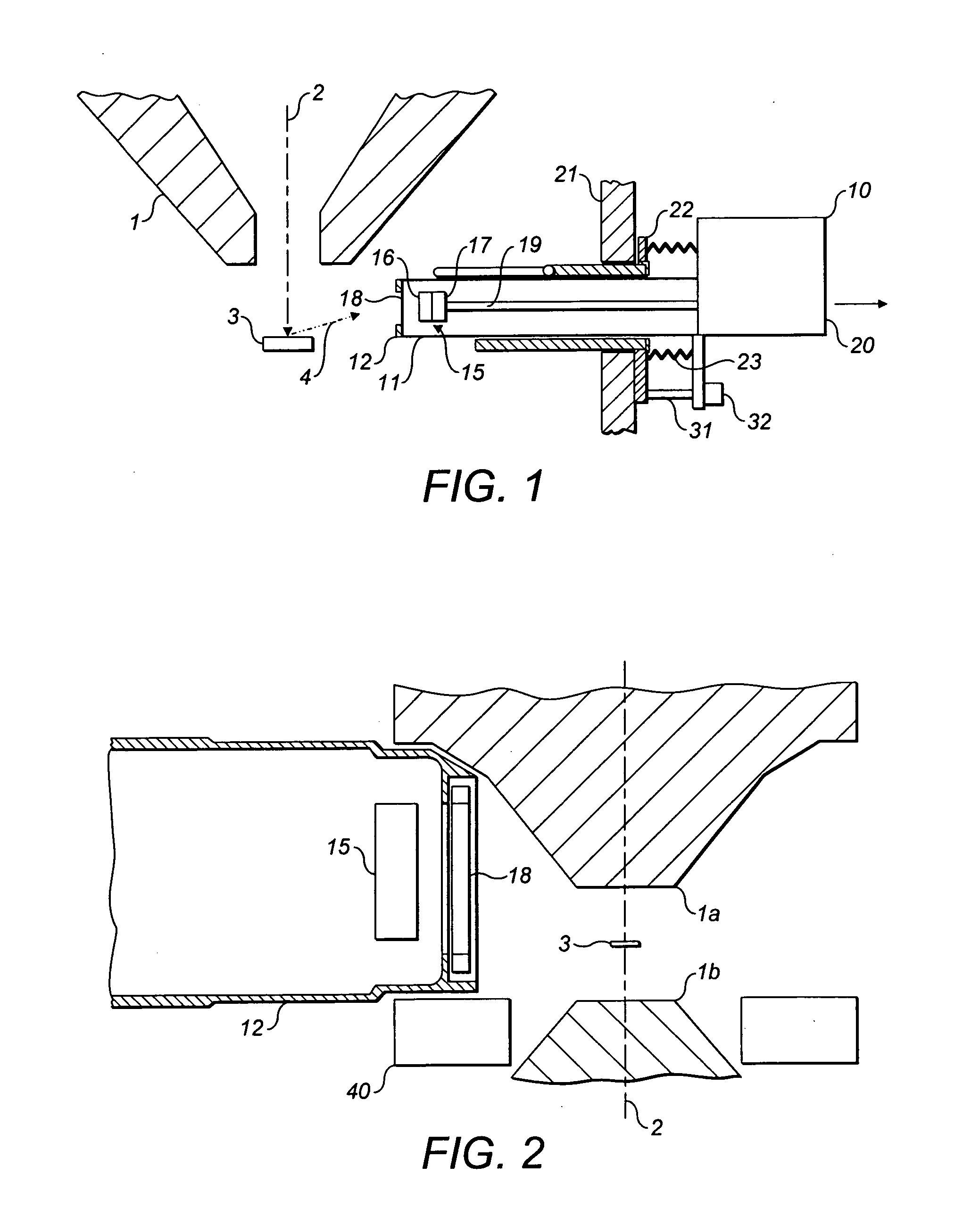
[0033]A transmission electron microscope arrangement with an example x-ray analyser according to the invention is shown in FIG. 1. The transmission electron microscope 100 has a lens pole piece 1a having a central aperture through which a focussed beam of electrons 2 impinges upon a specimen 3. A second lens pole piece 1b is positioned beneath the specimen in a known manner. The beam is accelerated by a strong electric field which provides electrons in the beam 2 with energies of typically at least 100 keV. The electrons are focussed by a number of electromagnetic lenses within the electron microscope column and pole piece. The relative arrangement of the pole pieces 1a,1b, beam 2 and specimen 3 is well known within the art. The high energy electrons cause x-rays and electrons 4 to be emitted / scattered from the specimen. In x-ray analysis it is these x-rays which are desired to be monitored and characterised using an x-ray analyser.

[0034]An x-ray analyser according to this example o...


PUM


Abstract

An x-ray analyser for a transmission electron microscope is described. The analyser has a silicon drift detector moveable in use between an analysis position and a retracted position. The analyser has a housing having an end portion within which the silicon drift detector is retained. The end portion is formed from a material with a relative magnetic permeability of less than 1.004. The analyser also has an automatic retraction system adapted to move the silicon drift detector from the analysis position to the retracted position upon receipt of a trigger signal indicative of a condition in which the power level received by the silicon drift detector from impinging x-rays or electrons is above a predetermined threshold.

Description

FIELD OF THE INVENTION[0001]The present invention relates to x-ray analysers for use with transmission electron microscopes (TEM).BACKGROUND OF THE INVENTION[0002]For x-ray analysis in an electron microscope (EM), an x-ray spectrum is measured by sensing and measuring the energies of individual x-ray photons emitted by a specimen when it is hit by a focussed electron beam. Each x-ray photon is an energetic particle and the energy is typically converted into charge using a solid state detector. Electrons which are scattered back from the sample, so called “backscattered electrons”, may also travel towards the x-ray detector.[0003]In the case of transmission electron microscopes (TEM), high energy electrons are used, typically having energies in excess of 100 keV, and the specimen is normally very thin so that the incident beam is transmitted right through the specimen. Since there is very little scattering within the specimen, x-rays and backscattered electrons emerge from a very sma...

Claims


Application Information

Patent Timeline
Patent Type & Authority Applications(United States)
IPC IPC(8): H01J37/285
CPCH01J37/244H01J37/26H01J2237/0203H01J2237/25H01J2237/2442H01J2237/2445H01J2237/024
Inventor BEWICK, ANGUSBHADARE, SANTOKH SINGH
Owner OXFORD INSTR NANOTECH TOOLS
Why Eureka
Try Eureka