Eureka AIR delivers breakthrough ideas for toughest innovation challenges, trusted by R&D personnel around the world.

Gas Turbine Engine With Accessory Gear Box

Active Publication Date: 2014-06-19
RAYTHEON TECH CORP
View PDF13 Cites 7 Cited by
  • Summary
  • Abstract
  • Description
  • Claims
  • Application Information

AI Technical Summary

Benefits of technology

This patent describes a gas turbine engine with a nacelle that has a bypass duct and a drive shaft that connects to the engine. The drive shaft drives two accessory gear boxes that are located between the inner and outer walls of the nacelle. The gear boxes include a starter for the engine and pumps to support the engine. The engine can be divided into two halves, and the gear boxes are located in the opposed halves. The technical effects of this design include improved performance and efficiency of the gas turbine engine.

Problems solved by technology

This has resulted in the radial thickness of the nacelle being relatively large.

Method used


Image

  • Gas Turbine Engine With Accessory Gear Box
  • Gas Turbine Engine With Accessory Gear Box
  • Gas Turbine Engine With Accessory Gear Box

Examples


Embodiment Construction

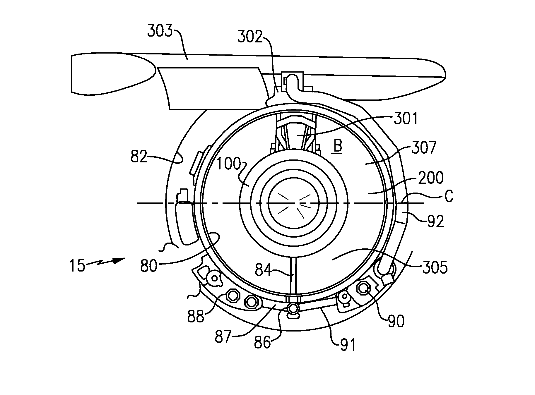
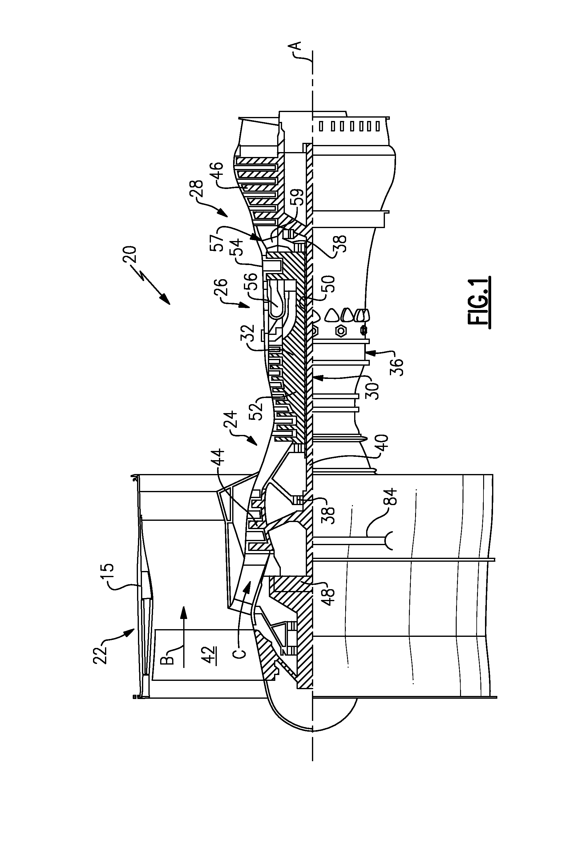
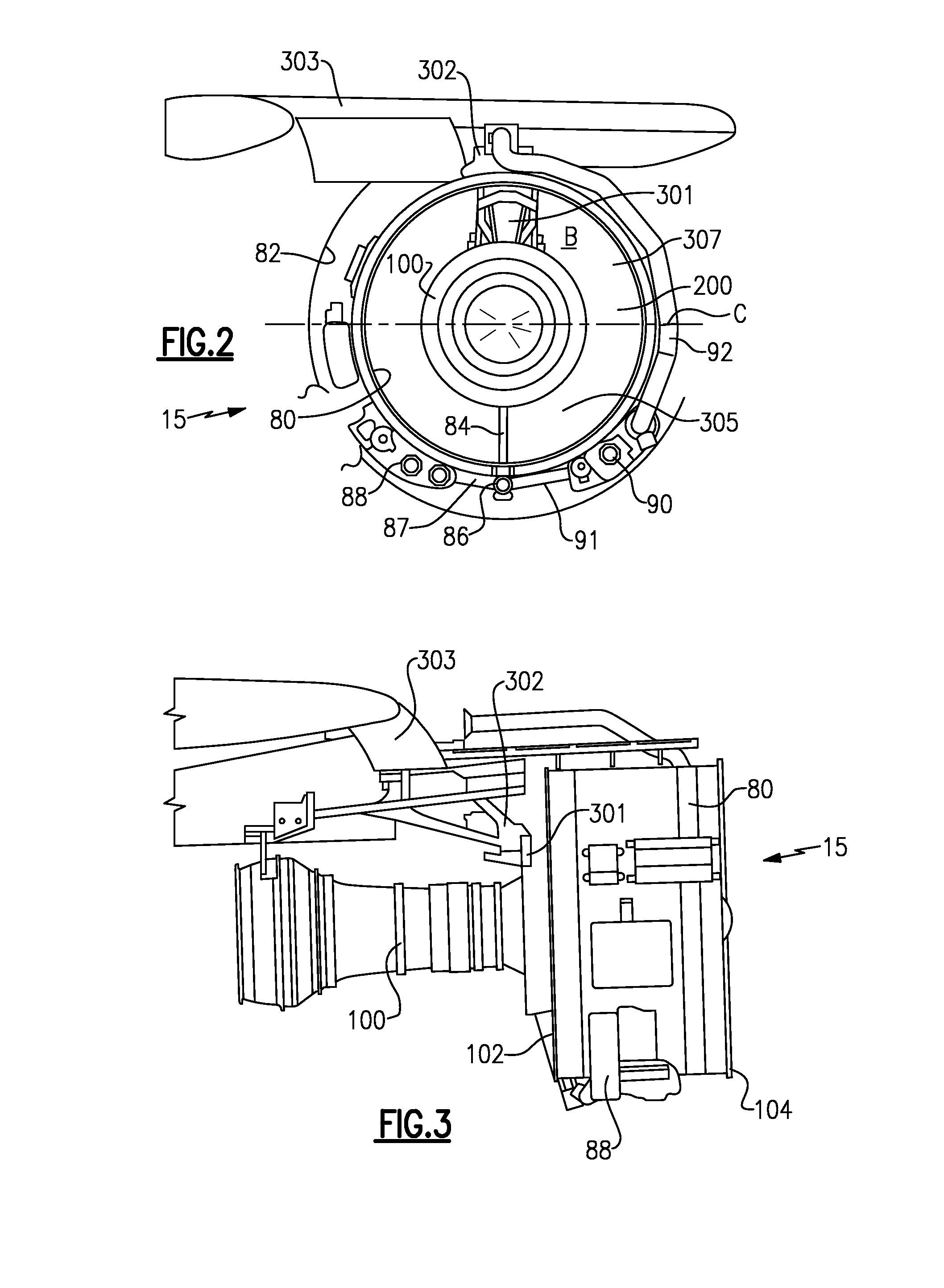
[0029]FIG. 1 schematically illustrates a gas turbine engine 20. The gas turbine engine 20 is disclosed herein as a two-spool turbofan that generally incorporates a fan section 22, a compressor section 24, a combustor section 26 and a turbine section 28. Alternative engines might include an augmentor section (not shown) among other systems or features. The fan section 22 drives air along a bypass flowpath B in a bypass duct defined within a nacelle 15, while the compressor section 24 drives air along a core flowpath C for compression and communication into the combustor section 26 then expansion through the turbine section 28. Although depicted as a turbofan gas turbine engine in the disclosed non-limiting embodiment, it should be understood that the concepts described herein are not limited to use with turbofans as the teachings may be applied to other types of turbine engines including three-spool architectures.

[0030]The engine 20 generally includes a low speed spool 30 and a high ...


PUM


Abstract

A nacelle for incorporation into a gas turbine engine has an inner wall defining a bypass duct, and an outer wall. At least one drive shaft extends through the inner wall. The at least one drive shaft is connected to a gas turbine engine receiving the nacelle. The at least one drive shaft is connected to drive at least two accessory gear boxes, with the at least two accessory gear boxes being received between the inner and outer walls of the nacelle. A gas turbine engine is also disclosed.

Description

BACKGROUND OF THE INVENTION[0001]This application relates to a gas turbine engine, wherein an accessory gear box is split into at least two portions driven by the main gas turbine engine, and positioned within a nacelle.[0002]Gas turbine engines are known, and typically include a fan delivering air into a bypass duct, and into a core engine. Air in the core engine passes through a compressor which compresses the air and delivers it into a combustor section. The air is mixed with fuel and ignited. Products of this combustion pass downstream over turbine rotors.[0003]The turbine rotors are driven to rotate, and drive the fan and compressor. In addition, power from the turbine rotors rotation is utilized to generate electricity, and to drive accessories to support the operation of the gas turbine engine.[0004]As an example, pumps for supplying liquid to the gas turbine engine are driven as accessories.[0005]Another accessory is a starter. The starter is typically provided with a fluid ...

Claims


Application Information

Patent Timeline
IPC IPC(8): F02C7/26
CPCF05D2260/4031F02K3/06F02C7/32F01D25/20F02C7/268F02C7/36F02C7/275F01D25/24F01D25/28Y02T50/60F01D15/12F01D17/105F02C3/04F02C7/06F02C7/22F05D2220/32F05D2240/60F05D2260/85
Inventor CLOFT, THOMAS G.GUKEISEN, ROBERT L.MERCIER, CLAUDE
Owner RAYTHEON TECH CORP
Why Eureka
Eureka Blog
Learn More