
Ignition plug

a plug and plug-in technology, applied in spark plugs, basic electric elements, electric devices, etc., can solve problems such as deterioration in the strength of the rear trunk portion, and achieve the effect of preventing the breakage of the thin-walled portion more reliably

Active Publication Date: 2014-06-19
NGK SPARK PLUG CO LTD
View PDF2 Cites 2 Cited by
  • Summary
  • Abstract
  • Description
  • Claims
  • Application Information

AI Technical Summary

Benefits of technology

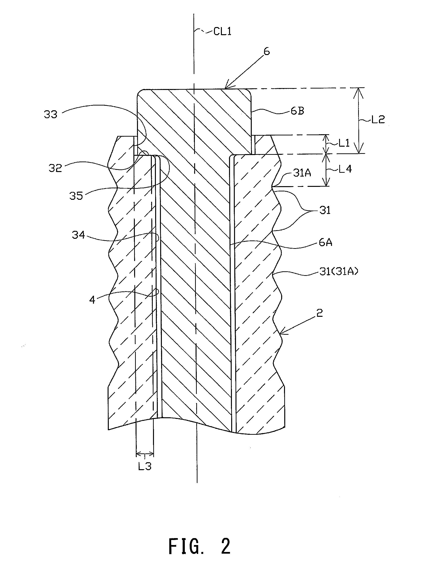
The patent text is trying to prevent breakage of a thin-walled portion in a configuration by a certain distance. It states that the distance between the location of generation of stress and the thin-walled portion is 0.5 mm or more, which provides a buffer to reduce the likelihood of stress being applied to the thin-walled portion. This results in a more reliable prevention of breakage.

Problems solved by technology

Hitting of the terminal electrode against the rear trunk portion may cause breakage of the rear trunk portion, or, even when the breakage is not reached, fine cracks may be formed in the rear trunk portion, resulting in deterioration in strength of the rear trunk portion.

Method used


Image

  • Ignition plug
  • Ignition plug
  • Ignition plug

Examples


Embodiment Construction

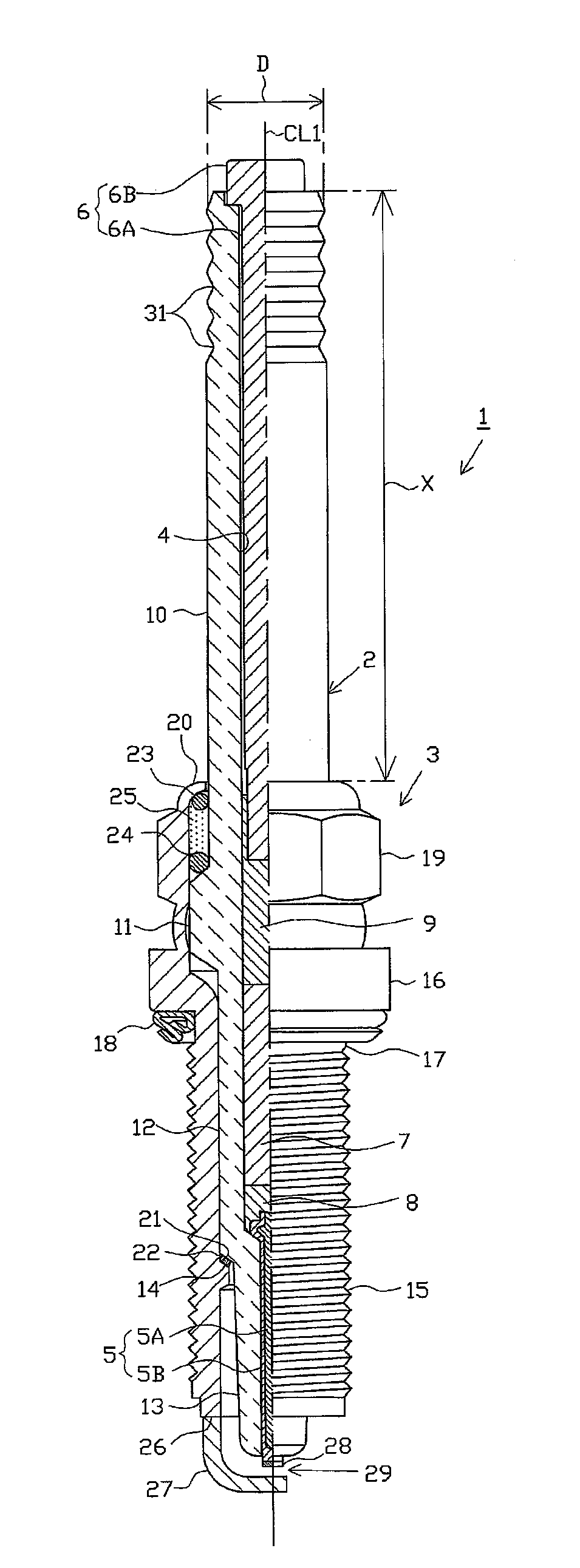
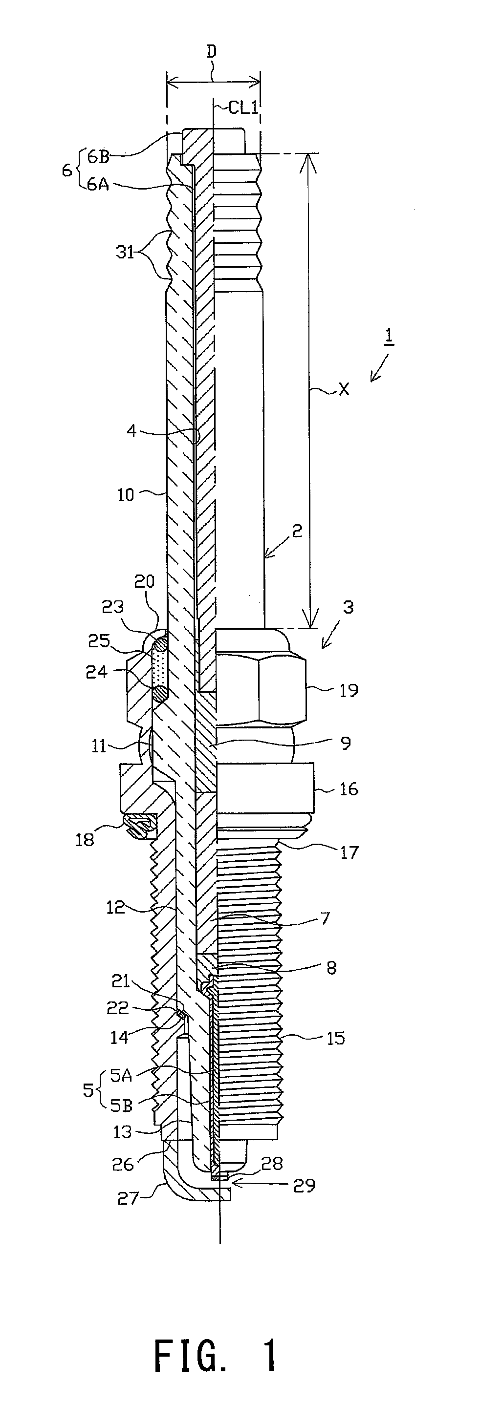
[0066]An embodiment of the present invention will next be described with reference to the drawings. FIG. 1 is a partially cutaway front view showing an ignition plug 1. In FIG. 1, the direction of an axis CL1 of the ignition plug 1 is referred to as the vertical direction. In the following description, the lower side of the spark plug 1 in FIG. 1 is referred to as the forward side of the spark plug 1, and the upper side as the rear side.

[0067]The ignition plug 1 includes a tubular ceramic insulator 2 and a tubular metallic shell 3, which holds the ceramic insulator 2 therein.

[0068]The ceramic insulator 2 is formed from alumina or the like by firing, as well known in the art. The ceramic insulator 2, as viewed externally, includes a rear trunk portion 10 formed at its rear side; a large-diameter portion 11 located forward of the rear trunk portion 10 and projecting radially outward; an intermediate trunk portion 12 located forward of the large-diameter portion 11 and being smaller in...


PUM


Abstract

An ignition plug includes a ceramic insulator having an axial bore, a metallic shell, and a terminal electrode. The terminal electrode has a leg portion inserted into a rear side of the axial bore, and a head portion formed on a rear side of the leg portion and having an outside diameter greater than that of the leg portion. The insulator includes a rear trunk portion exposed from the rear end of the metallic shell, which has a maximum outside diameter of 9.5 mm or less. The insulator has an end-surface seat portion located forward of its rear end and being in contact with the forward end surface of the head portion, and an outer circumferential portion into which at least a forward end portion of the head portion is inserted and which is located externally of the outer circumference of the head portion.

Description

CROSS-REFERENCE TO RELATED PATENT APPLICATIONS[0001]This application is a U.S. National Phase Application under 35 U.S.C. §371 of International Patent Application No. PCT / JP2012 / 067184, filed Jul. 5, 2012, and claims the benefit of Japanese Patent Application No. 2011-170643, filed on Aug. 4, 2011, all of which are incorporated by reference in their entirety herein. The International Application was published in Japanese on Feb. 7, 2013 as International Publication No. WO / 2013 / 018498 under PCT Article 21(2).FIELD OF THE INVENTION[0002]The present invention relates to an ignition plug for use in an internal combustion engine or the like.BACKGROUND OF THE INVENTION[0003]A spark plug for use in a combustion apparatus, such as an internal combustion engine, includes, for example, a tubular insulator having an axial bore, a center electrode provided in an inserted manner at a forward end portion of the axial bore, a terminal electrode provided in an inserted manner at the rear side of th...

Claims


Application Information

Patent Timeline
Patent Type & Authority Applications(United States)
IPC IPC(8): H01T13/20
CPCH01T13/20H01T13/34
Inventor KURONO, HIROKAZUHONDA, TOSHITAKA
Owner NGK SPARK PLUG CO LTD
Learn More