System for determining a magnetizing curve and rotor resistance of an induction machine and method of making same

a technology of magnetizing curve and rotor resistance, which is applied in the field of motor control, can solve the problems of large rotor resistance identification error, inability to realize locked rotor and no-load tests in some engineering applications, and high precision

Active Publication Date: 2014-06-19
EATON INTELLIGENT POWER LIMITED
View PDF5 Cites 17 Cited by
  • Summary
  • Abstract
  • Description
  • Claims
  • Application Information

AI Technical Summary

Benefits of technology

This patent describes two systems that use a DC-to-AC converter to identify the magnetic properties of an electric motor. One system uses a single phase of the motor while the other system uses both phases simultaneously. These systems can accurately measure the resistance of each part of the motor (the stator and rotor) by applying a specific type of electrical stimulation called a squarenoid waveform. By calculating these measurements and adjusting the motor's operation accordingly, it becomes possible to create precise controls over its performance.

Problems solved by technology

This patent relates to improving motor controls by accurately estimating the parameters of an induction machine. One challenge is finding ways to identify the magnetic field strength when there is no load or rotation present. Another problem is how to update the magnetization level during high-speed operations where the current levels become weaker. Different techniques like locking the rotor and applying specific frequencies have been attempted, but they come with their own limitations. There is a desire for better accuracy in calculating the actual magnetization curve of each individual machine.

Method used


Image

  • System for determining a magnetizing curve and rotor resistance of an induction machine and method of making same
  • System for determining a magnetizing curve and rotor resistance of an induction machine and method of making same
  • System for determining a magnetizing curve and rotor resistance of an induction machine and method of making same

Examples


Embodiment Construction

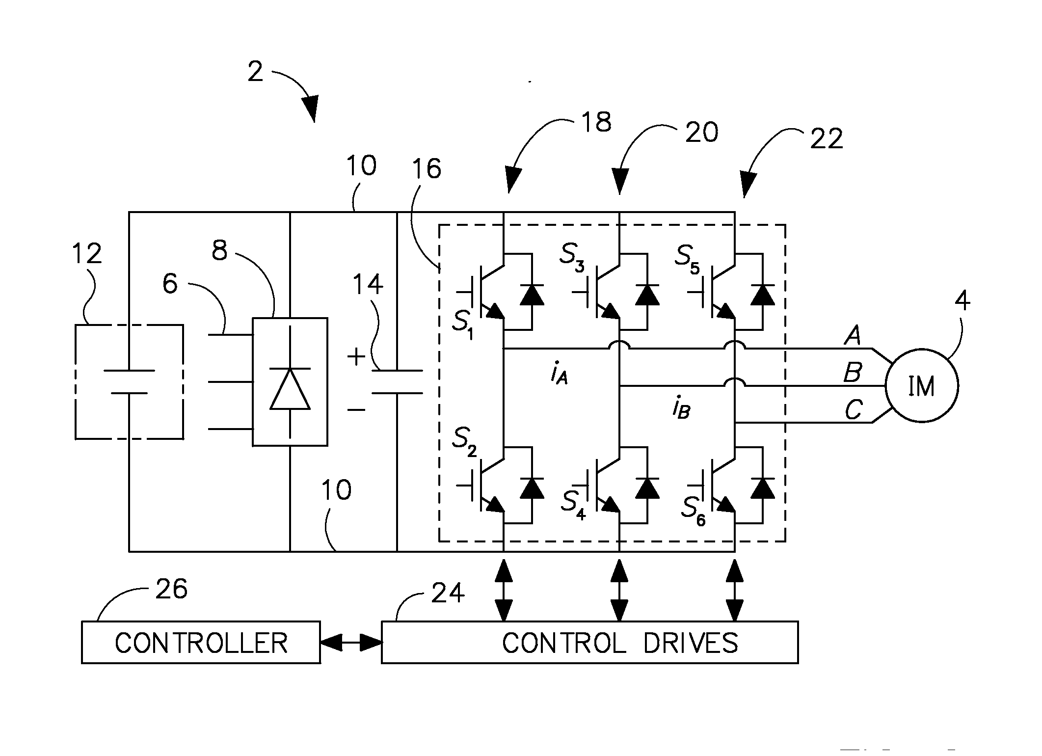
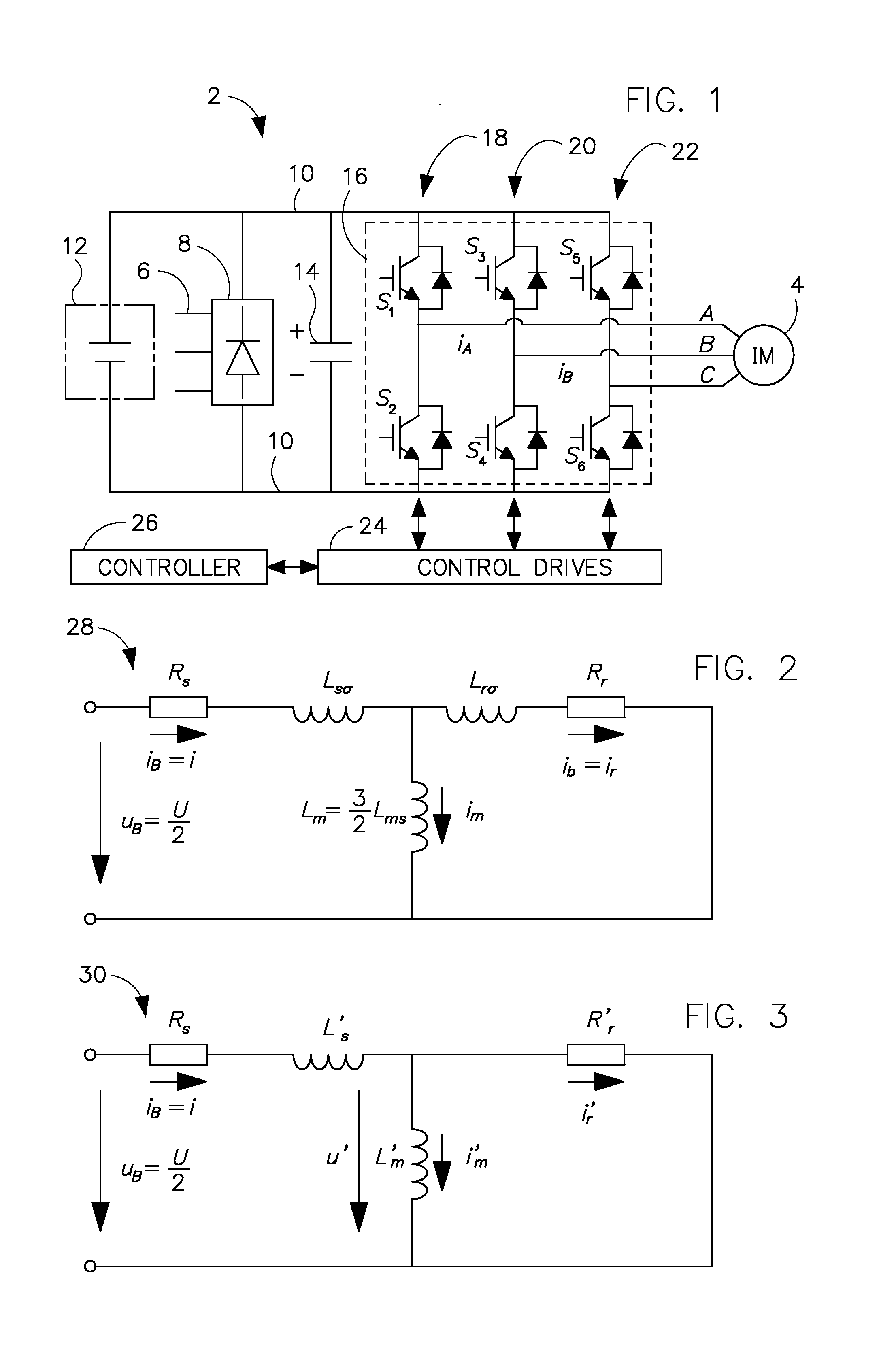
[0019]FIG. 1 is a circuit diagram of a control circuit 2 for an induction machine 4 according to an embodiment of the invention. In one embodiment, control circuit 2 includes an input 6 configured to receive AC power from and AC source such as an electrical grid. A rectifier assembly 8 is coupled to input 6 to convert the AC power to DC power and to supply the DC power to a DC bus 10. In an alternative embodiment, the DC power supplied to the DC bus 10 may be supplied by a DC energy source 12 (shown in phantom) such as a high-energy battery or the like. A filter capacitor 14 coupled to DC bus 10 may be used to provide a smoothing function for DC bus 10 and to filter high-frequency currents on DC bus 10.

[0020]A voltage inverter 16 is coupled to DC bus 10 and to induction machine 4. Preferably, voltage inverter 16 is a bi-directional voltage modification assembly configured to invert DC energy on DC bus 10 to AC energy usable by induction machine 4. Voltage inverter 16 includes six sw...


PUM

PropertyMeasurementUnit
Electrical resistanceaaaaaaaaaa
Electrical inductanceaaaaaaaaaa
Currentaaaaaaaaaa

Abstract

A system for identifying magnetizing inductance and rotor resistance of an induction machine comprises an induction machine comprising a rotor and a stator, a DC voltage bus, and a DC-to-AC voltage inverter coupled to the DC voltage bus and to the induction machine. The system also comprises a controller configured to cause the DC-to-AC voltage inverter to apply a square-wave excitation to a plurality of phases of the induction machine, determine a stator resistance of the stator of the induction machine based on the square-wave excitation, and determine a rotor resistance of the rotor of the induction machine based on the square-wave excitation. The controller is also configured to calculate a magnetizing curve for the induction machine based on the stator and rotor resistances and control the induction machine to operate based on the magnetizing curve.

Description


Claims


Application Information

Patent Timeline
Owner EATON INTELLIGENT POWER LIMITED
Why Eureka
Try Eureka