

Common mode filter
a filter and mode filter technology, applied in the direction of transformer/inductance details, inductance with magnetic core, inductance with inductance, etc., can solve the problems of large variation in characteristics and difficult to obtain high noise removal performance, and achieve high inductance and reduce the effect of mode conversion characteristics
- Summary
- Abstract
- Description
- Claims
- Application Information
AI Technical Summary
Benefits of technology
Problems solved by technology
Method used
Image

Examples
first embodiment
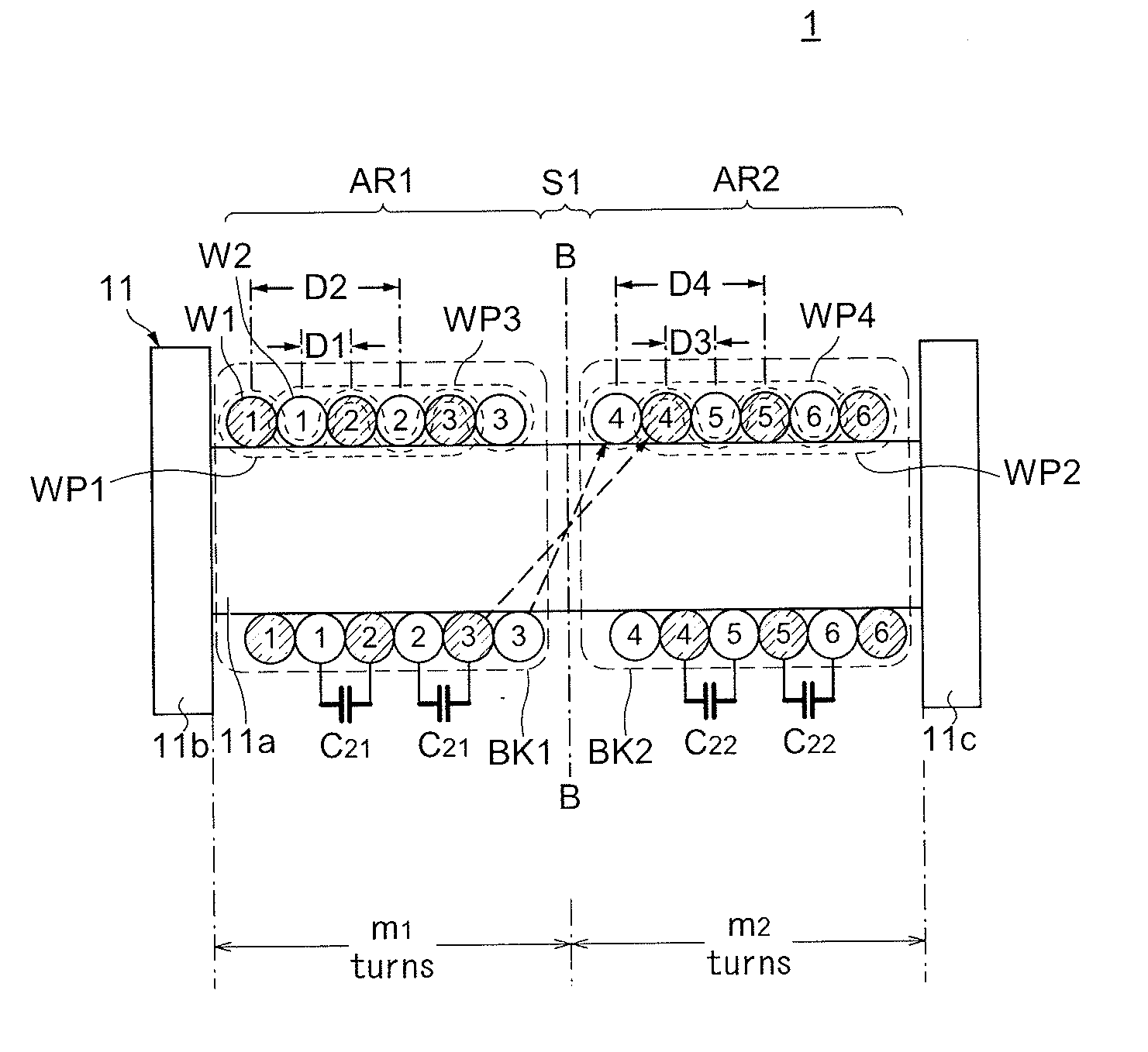
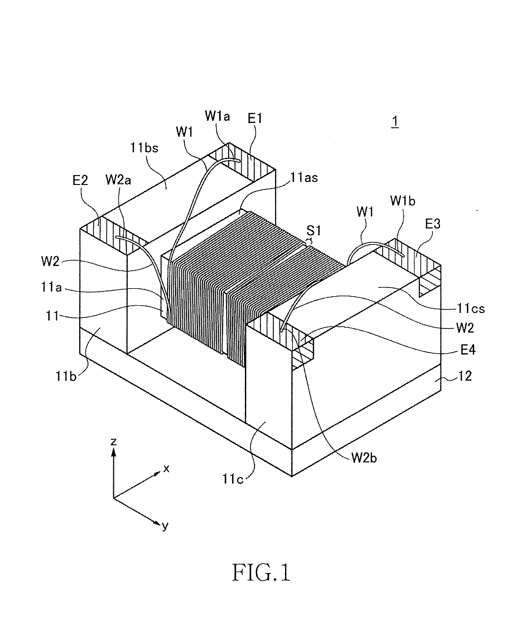
[0060]FIG. 1 is a schematic perspective view of an exterior structure of a surface-mount common mode filter 1 according to the present invention. In the present embodiments, as shown in FIG. 1, a direction in which a pair of flange portions 11b and 11c (described later) are opposed to each other is referred to as “y direction”, a direction perpendicular to the y direction in a plane of upper surfaces 11bs and 11cs (described later) is referred to as “x direction”, and a direction perpendicular to both the x direction and the y direction is referred to as “z direction”.
[0061]As shown in FIG. 1, the common mode filter 1 is configured by including a drum core 11, the plate core 12 attached to the drum core 11, and wires W1 and W2 (first and second wires) wound around the drum core 11. The drum core 11 includes a bar-shaped winding core portion 11a that is rectangular in cross section, and the flange portions 11b and 11c that are provided at both ends of the winding core portion 11a. Th...
second embodiment
[0090]FIG. 7 is a cross-sectional view schematically showing a winding structure of a common mode filter 2 according to the present invention. FIGS. 8A to 8D are schematic diagrams for explaining the winding structure of the common mode filter 2.
[0091]As shown in FIG. 7, the common mode filter 2 includes a pair of wires W1 and W2 wound around the winding core portion 11a of the drum core 11 by double-layer layer winding. The first wire W1 is sequentially wound from the one end in the longitudinal direction of the winding core portion 11a to the other end in the longitudinal direction to form a first coil and the second wire W2 is also sequentially wound from the one end in the longitudinal direction of the winding core portion 11a to the other end in the longitudinal direction to form a second coil that magnetically couples with the first coil. Because winding directions of the first and second coils are the same, a direction of flux generated by a current flowing through the first ...
third embodiment
[0107]FIG. 9 is a cross-sectional view schematically showing a winding structure of a common mode filter 3 according to the present invention. FIGS. 10A to 10D are schematic diagrams for explaining the winding structure of the common mode filter 3.
[0108]As shown in FIG. 9, the common mode filter 3 is characterized in that the second wire W2 forms a first winding layer directly wound on the surface of the winding core portion 11a and that the first wire W1 is wound on top of the first winding layer to form a second winding layer while surplus turns of the first wire W1 that cannot be wound on top of the first winding layer fall on both end sides of the winding core portion 11a, respectively. As in the second embodiment, m1=m2=4. A reason why a vertical relation between the first and second wires W1 and W2 is reversed from that in the second embodiment is to match final relations of the inter-wire distances D1 to D4 with those in the second embodiment and to simplify explanations of t...
PUM
 Abstract
Description
Claims
Application Information