Touch Panel Structure of Narrow Border

a touch panel and narrow border technology, applied in the field of touch panels, can solve the problems of increasing production cost, high cost of ito, and higher power consumption, and achieve the effect of saving material cost and manufacturing cost, and increasing the sensing signal strength and light penetration of the touch panel

Inactive Publication Date: 2014-06-19
SUPERC TOUCH CORP
View PDF13 Cites 0 Cited by
  • Summary
  • Abstract
  • Description
  • Claims
  • Application Information

AI Technical Summary

Benefits of technology

[0010]The object of the present invention is to provide a touch panel structure of narrow border, which can significantly increase the sensing signal strength and the light penetrability of a touch panel and also can greatly save the material cost and the manufacturing cost, and which is suitable for narrow border design in comparison with the prior art.

Problems solved by technology

However, the cost of ITO is high and, due to the optical characteristic of ITO, light penetration rate is decreased and the reflection rate is increased, resulting in higher power consumption, which is disadvantageous in developing the touch panels and increases the production cost.

Method used


Image

  • Touch Panel Structure of Narrow Border
  • Touch Panel Structure of Narrow Border
  • Touch Panel Structure of Narrow Border

Examples


Embodiment Construction

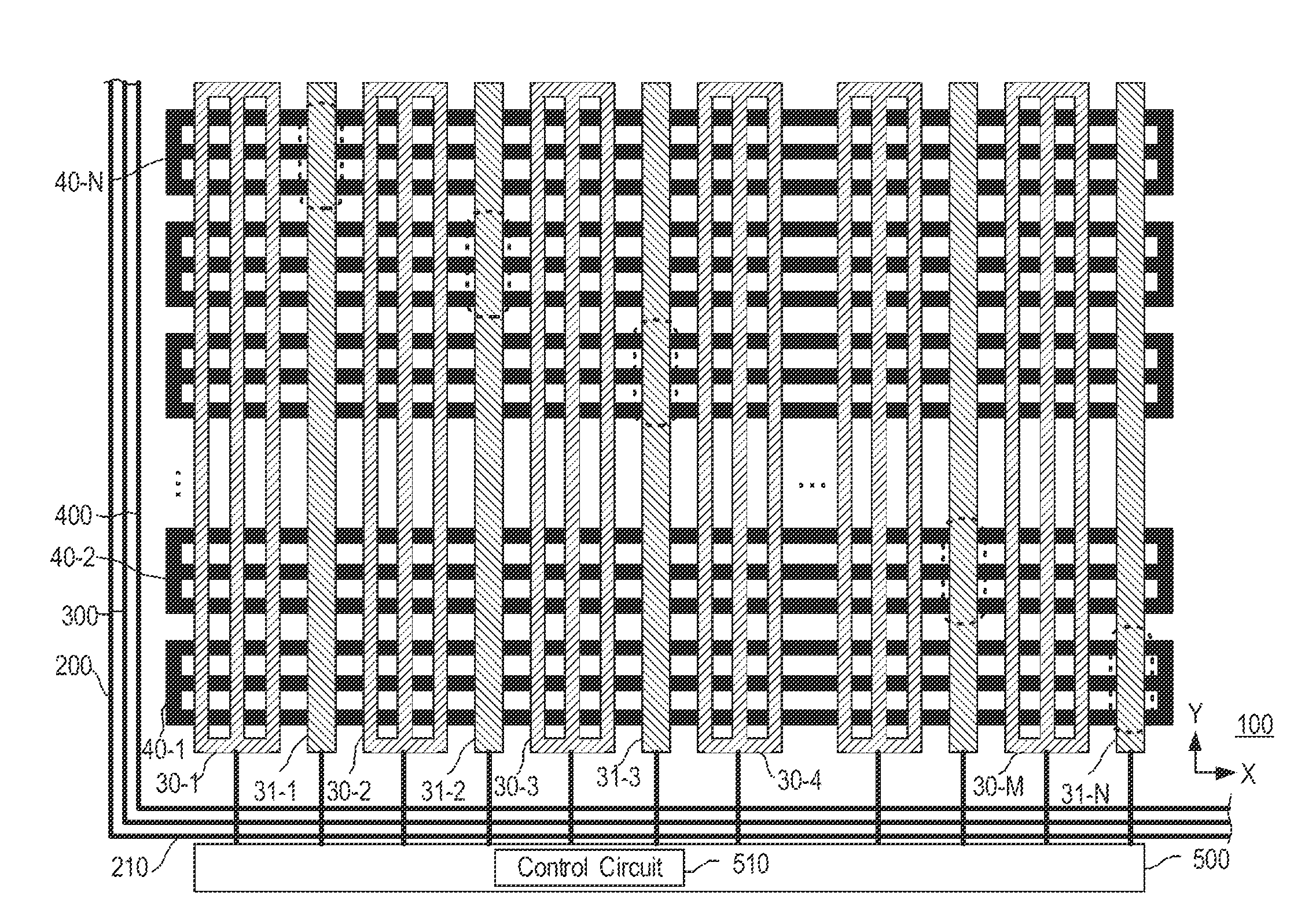
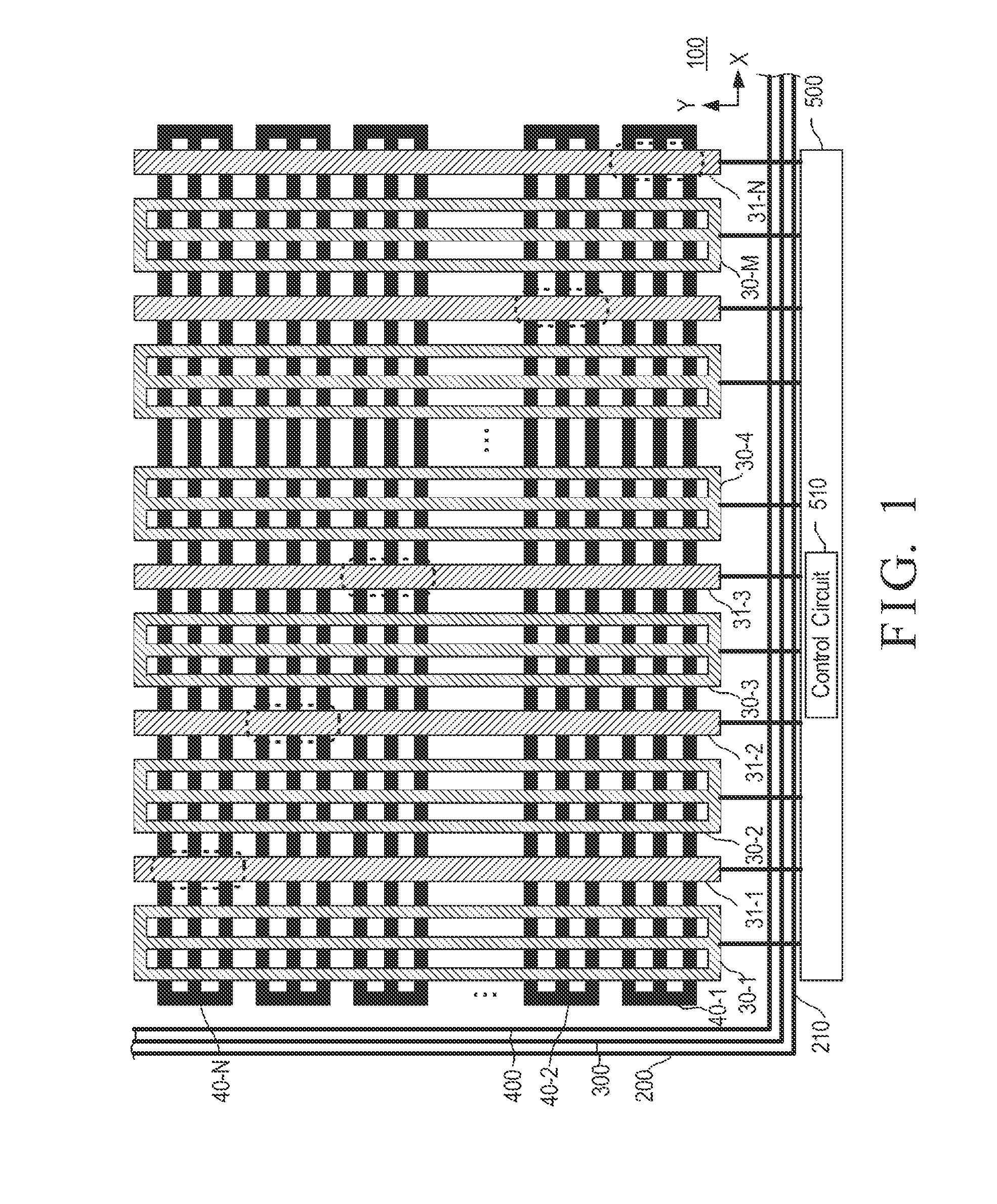
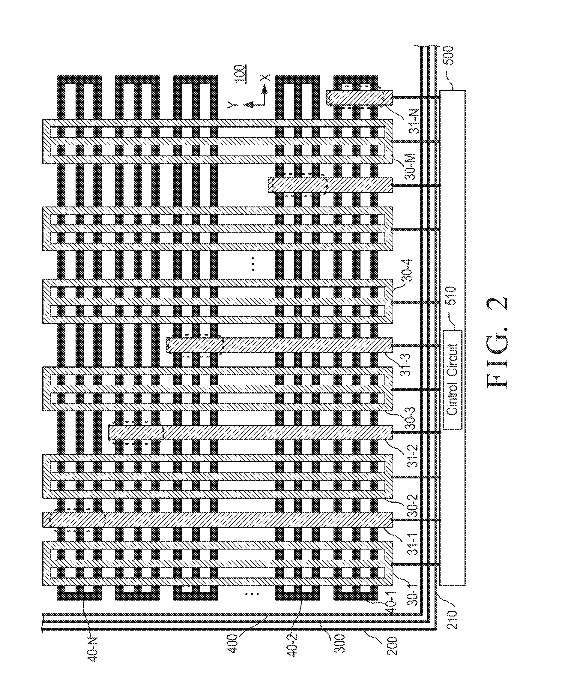
[0017]FIG. 1 is a schematic diagram of a touch panel structure of narrow border 100 according to an embodiment of the invention. The touch panel structure of narrow border 100 includes a panel 200, a first sensing electrode layer 300 and a second sensing electrode layer 400.

[0018]The panel 200 has an inner surface (not shown). The first sensing electrode layer 300 is formed on the inner surface and includes M first conductor line units 30-1, 30-2, . . . , 30-M and N connection lines 31-1, 31-2, . . . , 31-M arranged in a first direction (Y-direction) for detecting whether there is an external object approached, where M and N are each a positive integer. The N connection lines 31-1, 31-2, . . . , 31-N are made of conductive metal material.

[0019]The second sensing electrode layer 400 is formed on the inner surface and includes N second conductor line units 40-1, 40-2, . . . , 40-N arranged in a second direction (X-direction). When performing touch sensing and receiving touch driving s...


PUM


Abstract

A touch panel structure of narrow border includes a panel having an inner surface, a first sensing electrode layer and a second sensing electrode layer formed on the inner surface. The first sensing electrode layer includes plural first conductor line units and plural connection lines arranged in a first direction for detecting whether there is an external object approached according to a touch driving signal. The second sensing electrode layer includes plural second conductor line units arranged in a second direction. When performing a touch sensing and receiving the touch driving signal, each of the second conductor line units makes use of a corresponding connection line to be extended to one side of the panel.

Description

BACKGROUND OF THE INVENTION[0001]1. Field of the Invention[0002]The present invention relates to the technical field of touch panels and, more particularly, to a touch panel structure of narrow border.[0003]2. Description of Related Art[0004]Modern consumer electronic apparatuses are typically equipped with touch panels for use as their input devices. According to different sensing manners, the touch panels can be classified into resistive type, capacitive type, acoustic type, and optical type.[0005]The principle of touch panels is based on different sensing manners to detect a voltage, current, acoustic wave, or infrared to thereby detect the coordinates of touch points on a screen where a finger or other medium touches. For example, a resistive touch panel uses a potential difference between the upper and lower electrodes to compute the position of a pressed point for detecting the location of the touch point, and a capacitive touch panel uses a capacitance change generated in an ...

Claims


Application Information

Patent Timeline
Patent Type & Authority Applications(United States)
IPC IPC(8): G06F3/044
CPCG06F3/044G06F2203/04112G06F3/0445G06F3/0446G06F3/0448
Inventor LEE, HSIANG-YU
Owner SUPERC TOUCH CORP
Why Eureka
Try Eureka