Printing fluid supply device and printing fluid cartridge
a technology of printing fluid supply device and printing fluid cartridge, which is applied in printing and other directions, can solve the problems of difficulty in achieving high dimensional precision of ink supply devi
- Summary
- Abstract
- Description
- Claims
- Application Information
AI Technical Summary
Benefits of technology
Problems solved by technology
Method used
Image
Examples
first modified embodiment
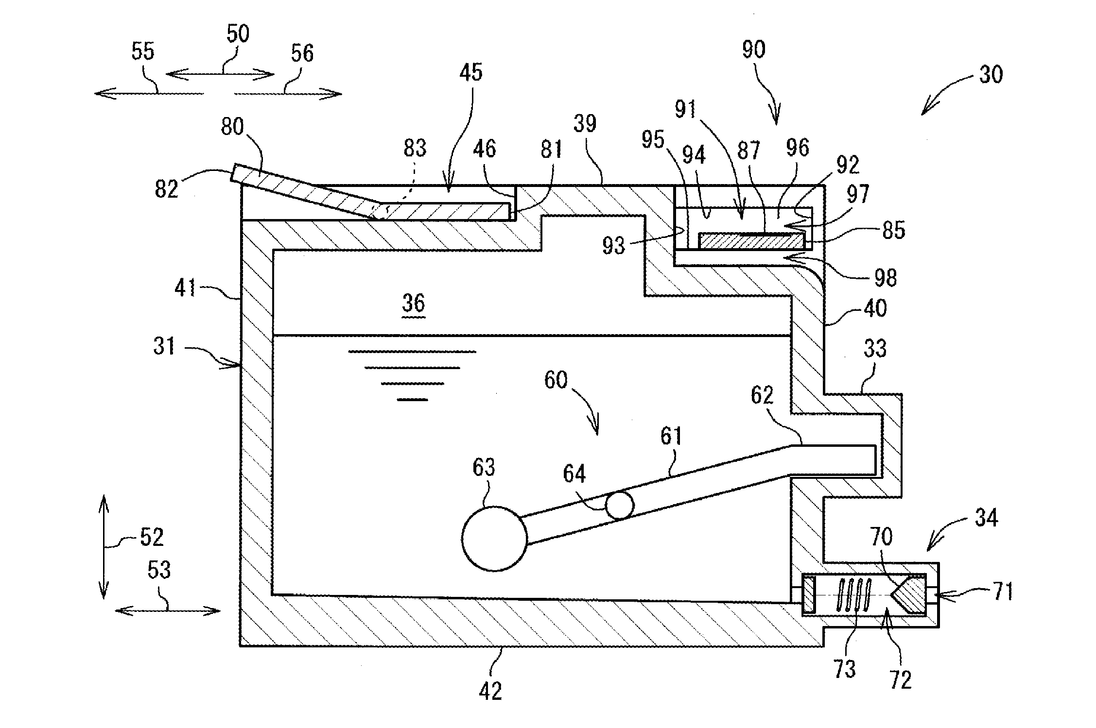
[0089]Referring to FIGS. 9A and 9B, a first modified embodiment will be described. Detailed descriptions common to the above-described embodiment will be omitted and differences from the above-described embodiment will be mainly described. The first modified embodiment differs from the above-described embodiment in that the ink cartridge 30 comprises a board cover member 130 positioned in the upper space 97 and a board cover member 131 positioned in the lower space 98.
[0090]Referring to FIGS. 9A and 9B, the board cover member 130 is resiliently supported by a coil spring 132. One end of the coil spring 132 is linked to a surface of the board cover member 130, which surface faces in the removal direction 55, and the other end of the coil spring 132 is linked to an outer surface of the main body 31, which outer surface faces in the insertion direction 56. The board cover member 130 is an example of a first movable member. When the ink cartridge 30 is not mounted to the cartridge mount...
second modified embodiment
[0098]Next, referring to FIG. 10 a second modified embodiment will be described. Detailed descriptions common to the above-described embodiment will be omitted and differences from the above-described embodiment will be mainly described. The second modified embodiment differs from the above-described embodiment in that the ink supply device 100 comprises a positioning portion 106 configured to determine the positioning of the IC board 85 relative to the cartridge mounting portion 110 in the width direction (left-right direction) 51. That is, in the second modified embodiment, a movable distance of the IC board 85 in the width direction (left-right direction) 51 relative to the main body 31 does not necessarily need to be less than the width of each of the electrodes 86, 87, and 88 in the width direction (left-right direction) 51.
[0099]Referring to FIG. 10A, the positioning portion 106 comprises a notch portion 107 formed at the central part of the IC board 85 in the width direction ...
third modified embodiment
[0102]Referring to FIGS. 11A to 11D, a third modified embodiment will be described with reference to FIG. 11. Detailed descriptions common to the above-described embodiment will be omitted and differences from the above-described embodiment will be mainly described. The third modified embodiment differs from the above-described embodiment in that the rear wall surface 93, which defines the groove 91, is resiliently movable in the depth direction (front-rear direction) 53. The rear wall surface 93 in the above-described embodiment is the same plane as the outer surface of the main body 31, which outer surface faces in the insertion direction 56 and closes the space formed in the IC board holding portion 90 in the removal direction 55. By contrast, the rear wall surface 93 in the third modified embodiment is provided on a wall member 135, which is movable in the groove 91 in the insertion / removal direction 50.
[0103]More specifically, referring to FIGS. 11A to 11D, the IC board holding...
PUM
 Abstract
Description
Claims
Application Information
 - R&D
- Intellectual Property
- Life Sciences
- Materials
- Tech Scout
- Unparalleled Data Quality
- Higher Quality Content
- 60% Fewer Hallucinations
Browse by: Latest US Patents, China's latest patents, Technical Efficacy Thesaurus, Application Domain, Technology Topic, Popular Technical Reports.
© 2025 PatSnap. All rights reserved.Legal|Privacy policy|Modern Slavery Act Transparency Statement|Sitemap|About US| Contact US: help@patsnap.com


