Connector

A connector, connected to technology, applied in the direction of a device to relieve stress at a wire connection, etc., can solve problems such as connection failure and reduction of coaxial cable flexibility

Inactive Publication Date: 2005-12-14
JAPAN AVIATION ELECTRONICS IND LTD
View PDF1 Cites 3 Cited by
  • Summary
  • Abstract
  • Description
  • Claims
  • Application Information

AI Technical Summary

Problems solved by technology

[0009] In addition, although the surface of the ground rod electrically contacts the metal external part provided in the connector, it is prone to connection failure due to the use of flux in soldering
Metal plates can be used in place of ground rods, but are equally prone to connection failure due to the use of flux in the soldering
[0010] The problem is that although traditionally the outer conductor of a coaxial cable is electrically connected and mechanically held by soldering, however, the bendability of the coaxial cable is reduced to the extent that the solder is lifted as the wet solder travels along the outer conductor

Method used


Image

  • Connector
  • Connector
  • Connector

Examples


Embodiment Construction

[0047] In order to facilitate the understanding of the present invention, prior to describing the embodiments of the present invention, a conventional connector will be described.

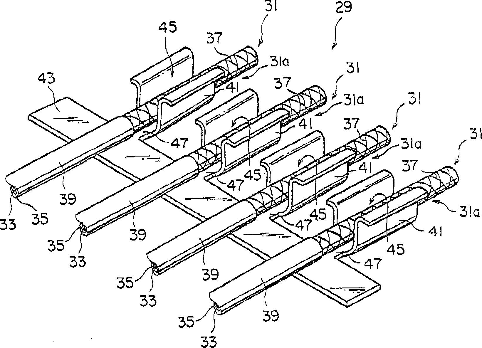
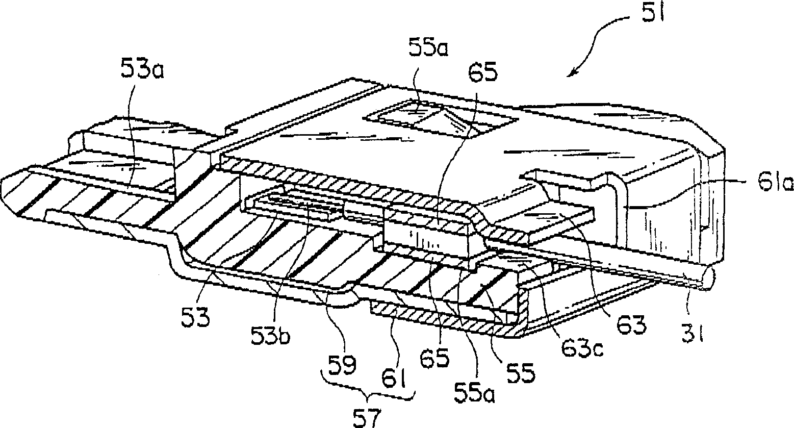
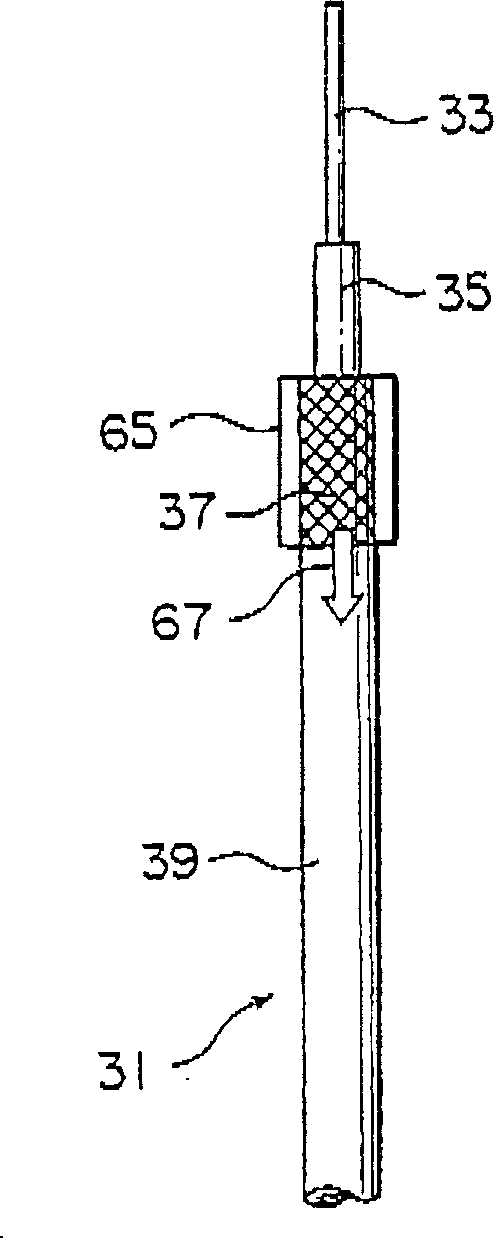
[0048] refer to figure 1, the conventional coaxial cable connector 29 disclosed in Patent Document 1 is adapted to be electrically connected to outer conductors 37 of a plurality of coaxial cables 31 arranged in a row at a predetermined pitch. The coaxial cable connector 29 has a structure in which terminals 41 each having a U-shaped cross-section and for fitting a corresponding one of the outer conductors 37 of the supporting coaxial cable 31 are integrally arranged in a row. The outer conductor is exposed by partially cutting away the jacket 39 of the coaxial cable 31, and, through the fitting engagement between the outer conductor 37 and the terminal 41, the outer conductor 37 and the terminal 41 are collectively electrically connected together. Alternatively, the end portions 31a of the coaxia...


PUM


Abstract

A connector for connecting to an electrical cable includes a retaining member for aligning and retaining the electrical cable. The holding part has a main body part and a rod part. The body portion has a plurality of fixing portions for fixedly holding the rod member. The cable is securely clamped between the body portion and the bar member.

Description

technical field [0001] This invention relates to connectors, and more particularly to connectors having structures to hold thin coaxial cables. Background technique [0002] Conventionally, in an electrical connector, there is a structure for holding a plurality of coaxial cables described in Japanese Unexamined Patent Application Publication (JP-A) H11-260439 (hereinafter referred to as Patent Document 1). The coaxial cable connector of Patent Document 1 is configured such that the respective terminals having a U-shaped cross-section and for fitting a corresponding one of the outer conductors supporting the coaxial cable are integrally arranged in a row, thereby collectively realizing the electrical connection of the coaxial cable, wherein The coaxial cable is exposed by partially cutting its coating or jacket. Alternatively, the ends of the coaxial cables horizontally arranged coaxially at predetermined intervals are respectively fitted in the corresponding terminals with...

Claims


Application Information

Patent Timeline
Patent Type & Authority Applications(China)
IPC IPC(8): H01R13/58
Inventor 桥口彻甲斐圭造菊池正幸铃木守加藤富和小出清人
Owner JAPAN AVIATION ELECTRONICS IND LTD
Why Eureka
Try Eureka