
System and method for autostereoscopic imaging using holographic optical element

a technology of holographic optical elements and autostereoscopic imaging, which is applied in the field of system and method for creating and displaying autostereoscopic threedimensional images using holographic optical elements, can solve the problems of poor color reproduction of projected images, affecting horizontal resolution and light output, and affecting so as to improve the uniformity of illumination and color balance, improve the effect of color fidelity during playback, and improve system efficiency

Inactive Publication Date: 2014-06-19
KUGHN ABSOLUTE HLDG
View PDF18 Cites 12 Cited by
  • Summary
  • Abstract
  • Description
  • Claims
  • Application Information

AI Technical Summary

Benefits of technology

The patent describes systems and methods for creating autostereoscopic images that can be viewed without glasses or headgear. The systems use a holographic optical element (HOE) recorded using coherent light from at least three wavelengths. The HOE is illuminated by a diverging reference and object beam, which eliminates the need for a spherical or parabolic concave mirror to illuminate it during recording. The system also includes a directional diffuser to improve transmission efficiency and reduce stray light. The patent also describes the use of an aperture and cylindrical lens to improve the mapping of the object beam to the aspect ratio of the HOE. The systems provide real-time stereo images that can be viewed without viewing aids and can detect and synchronize with viewer movement. The use of a reflection holographic element provides higher resolution and improved color fidelity.

Problems solved by technology

However, horizontal resolution and light output are adversely impacted with this approach, and the “sweet spot”, or zone where one can best visualize a stereoscopic image, is very small.
As such, three-dimensional imaging systems based on parallax barriers and Fresnel lenses, as well as those using lenticular sheets, have generally fallen short of user expectations.
However, the region of color fidelity is generally of very limited extent such that any vertical movement by the viewer results in color shifting and poor color reproduction of the projected image.
Such effects are distracting and make this approach unsuitable for a variety of applications, particularly where color fidelity is desired, such as in medical imaging, entertainment, and a variety of other applications.
This introduces numerous challenges due to the frequency (or wavelength) sensitivity / dependence of the recording medium and various optical elements used in both the recording and playback of the HOE.
However, this approach introduces additional complexities associated with having multiple recording set-ups, precise control of environmental conditions during multiple exposures, alignment or registration of the layers, and the like.
However, the pixel size and fill ratio or packing density limits the resulting resolution, which may not be acceptable for smaller screens for use in personal entertainment or gaming, or in more demanding applications where high resolution is desired, such as in medical imaging, for example.
Such requirements present additional challenges for autostereoscopic display systems, which may use various types of projectors to illuminate the HOE screen with the left-eye and right-eye images.
Depending on the particular projectors being used, some digital image correction may be provided, although this generally results in reduced resolution of the autostereoscopic system.

Method used


Image

  • System and method for autostereoscopic imaging using holographic optical element
  • System and method for autostereoscopic imaging using holographic optical element
  • System and method for autostereoscopic imaging using holographic optical element

Examples


Embodiment Construction

)

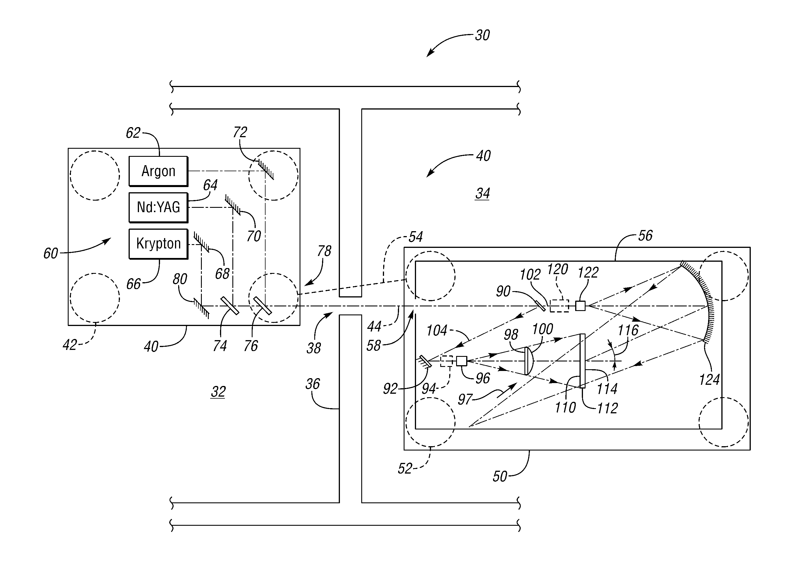
[0060]As those of ordinary skill in the art will understand, various features of the embodiments illustrated and described with reference to any one of the Figures may be combined with features illustrated in one or more other Figures to produce alternative embodiments that are not explicitly illustrated or described. The combinations of features illustrated provide representative embodiments for typical applications. However, various combinations and modifications of the features consistent with the teachings of the present disclosure may be desired for particular applications or implementations. The representative embodiments used in the illustrations relate generally to an autostereoscopic display system and method capable of displaying a stereo image in real-time using either live stereo video input, such as provided by a stereo camera, endoscope, etc., or a standard video input processed to generate simulated stereo video that is perceived as a three-dimensional image by one o...


PUM


Abstract

Systems and methods for creating an autostereoscopic display include a holographic optical element (HOE) recorded using coherent light divided into diverging reference and object beams that illuminate the HOE from opposite sides. The object beam passes through first and second diffusers with one diffuser being a directional diffuser to more uniformly illuminate the HOE. Optic elements may be used to more closely match beam diameters and / or profiles of the recording wavelengths. Baffles may be positioned on opposite sides of the HOE with openings aligned proximate the reference beam and object beam paths, respectively, to reduce stray reflections and provide ambient air flow attenuation or damping. One or more edges of the HOE are masked to reduce or prevent stray light from entering and reflecting within the HOE during recording.

Description

CROSS-REFERENCE TO RELATED APPLICATIONS[0001]This application is a continuation-in-part of commonly owned and copending U.S. patent application Ser. No. 12 / 883,348 filed Sep. 16, 2010, titled “System and Method for Autostereoscopic Imaging” which claims the benefit of U.S. Ser. No. 61 / 244,880 filed Sep. 22, 2009 and is a continuation-in-part of commonly owned and copending U.S. patent application Ser. No. 12 / 408,447 filed Mar. 20, 2009, and Ser. No. 12 / 428,118 filed Apr. 22, 2009, the disclosures of all of which are incorporated by reference in their entirety.BACKGROUND[0002]1. Field[0003]The present disclosure relates to systems and methods for creating and displaying autostereoscopic three-dimensional images using a holographic optical element.[0004]2. Background Art[0005]Stereoscopic display devices separate left and right images corresponding to slightly different views or perspectives of a three-dimensional scene or object and direct the images to a viewer's left and right eye,...

Claims


Application Information

Patent Timeline
Patent Type & Authority Applications(United States)
IPC IPC(8): G02B27/22G02B5/32G03H1/02G03H1/04
CPCG02B5/32G02B13/22G03H1/04G03H2001/0439H04N13/302H04N13/366G03H1/0272G03H1/0402
Inventor DELL'EVA, MARK L.BJELKHAGEN, HANS INGMAR
Owner KUGHN ABSOLUTE HLDG
Learn More