Radio communication terminal and radio communication method

a radio communication terminal and radio communication technology, applied in the field of radio communication terminals and radio communication methods, can solve the problems of ue not being able to maintain communication with enb, the measurement operation of measuring the quality of rn does not function at ue, and the ue cannot achieve the effect of high accuracy and measurement quality in communication

Active Publication Date: 2014-06-19
SUN PATENT TRUST
View PDF10 Cites 0 Cited by
  • Summary
  • Abstract
  • Description
  • Claims
  • Application Information

AI Technical Summary

Benefits of technology

The present invention is about a radio communication terminal and method that allows for accurate measurement of communication quality during handovers in subframes that are not used for backhaul (which is when signals are transmitted in a wireless network). This improves the overall efficiency and reliability of the network.

Problems solved by technology

Here, when the backhaul channel and the access channel are allocated in the same frequency bandwidth, if RN performs transmission and reception at the same time, loop-back interference occurs.
However, if RN transmits no signal in the subframes where RN serves as the backhaul channel, a problem occurs that a measurement operation of measuring the quality of RN does not function at UE of LTE which has not ascertained the presence of RN.
In this regard, in a mobile communication system, a situation occurs in which, when UE communicates with a certain eNB, received power from eNB is lowered due to movement of UE, change in the surrounding environment or the like and thus UE cannot maintain communication with eNB.

Method used


Image

  • Radio communication terminal and radio communication method
  • Radio communication terminal and radio communication method
  • Radio communication terminal and radio communication method

Examples


first embodiment

[0054]Hereinafter, a first embodiment of the present invention will be described with reference to FIGS. 1 to 7.

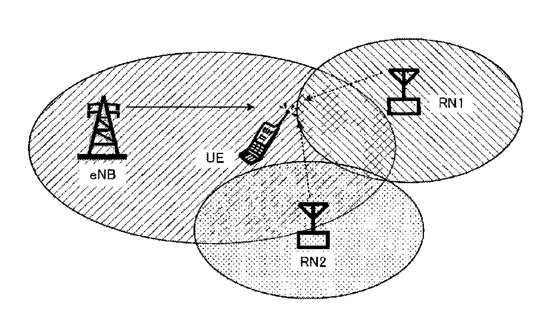
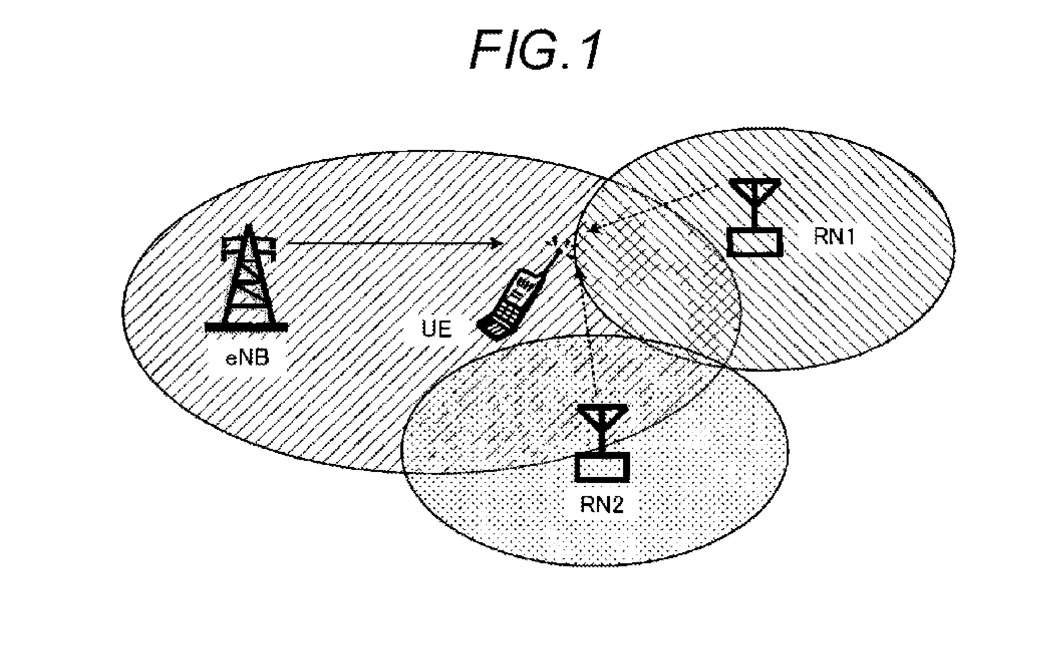
[0055]Firstly, a radio relay system in the first embodiment of the present invention will be described. FIG. 1 is a diagram illustrating the radio relay system according to the first embodiment of the present invention. In FIG. 1, eNB represents a base station (base station apparatus) 200, RN1 and RN2 represent relay stations 310 and 320, and UE represents a radio communication terminal 100, respectively.

[0056]Hereinafter, in the first embodiment, the radio communication terminal 100 is referred to as UE, the base station 200 is referred to as eNB, and the relay stations 310 and 320 are referred to as RN1 and RN2, respectively.

[0057]Hereinafter, in the first embodiment, as studied in LTE-A, RN1 and RN2 have an individual cell ID, in a similar way to eNB. Thus, when viewed from UE, RN1 and RN2 may be considered as one cell, respectively, in a similar way to eNB.

[0058]Herein...

first example

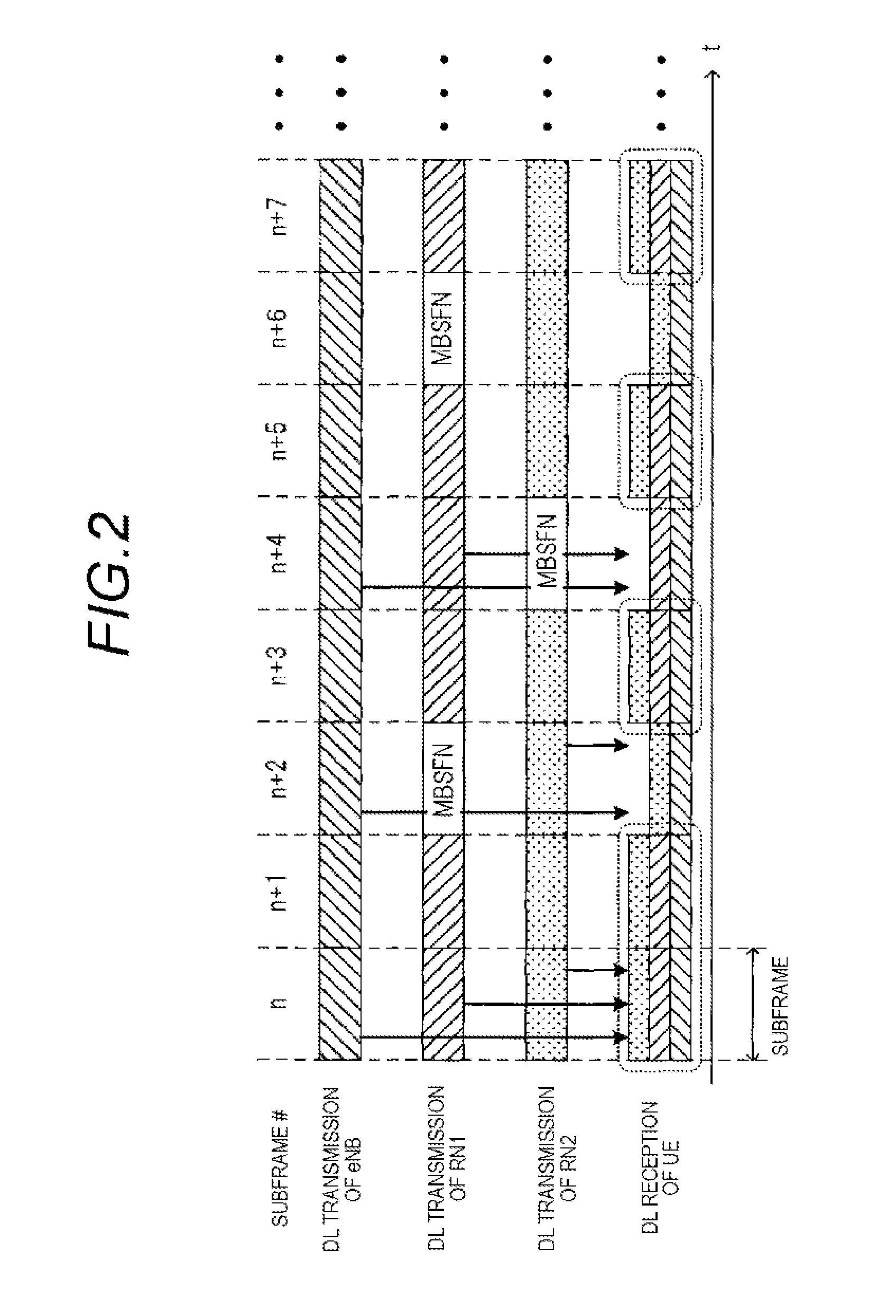
[0118]As a first example of the method of detecting the subframes where measurement should be performed using the received power, the following method is used. Firstly, UE measures the received power over the plurality of subframes, and detects a subframe where the received power is the largest. UE sets a threshold which becomes a predetermined power difference with reference to the largest received power, and detects a subframe where the received power is lower than the threshold as the “MBSFN subframe that RN uses as the backhaul” in the neighbor RNs. UE sets subframes except for the detected “MBSFN subframe that RN uses as the backhaul” in the neighbor RNs, as the subframes where measurement should be performed.

[0119]For example, where the largest received power of the detected subframe is Pmax, the predetermined power difference is Pd, the threshold is Pth, and the received power of the n-th subframe is Pn, UE detects a subframe n which satisfies the following Formula 1 as the “...

second example

[0120]Further, as a second example of the method of detecting the subframes where measurement should be performed using the received power, the following method may be also used. Firstly, UE measures and averages the received power over the plurality of subframes, and detects an average received power. UE sets a threshold which becomes a predetermined power difference with reference to the average received power, and compares the threshold and the received power of each subframe. Further, UE detects a subframe where the received power is lower than the threshold as the “MBSFN subframe that RN uses as the backhaul” in the neighbor RNs. UE sets subframes except for the detected “MBSFN subframe that RN uses as the backhaul” in the neighbor RNs, as subframes where measurement should be performed.

[0121]For example, where the average received power is Pave, UE detects a subframe n which satisfies the following Formula 2 as the “MBSFN subframe that RN uses as the backhaul” in the neighbor ...


PUM


Abstract

Provided is a radio communication terminal which is capable of measuring quality in communication with a handover destination with high accuracy. The radio communication terminal is capable of communicating with a base station or a relay node, and includes: a receiver which receives control information including information relating to measurement of measuring quality of a neighbor cell; an extractor which extracts information on a subframe where the measurement should be performed, which is a subframe where only transmission of a signal from the relay node connected to the base station is performed, from the information relating to the measurement; a measurement section which performs the measurement, on a subframe basis, based on the extracted information on the subframe where the measurement should be performed; and a transmitter which transmits a result of the measurement to the base station or the relay node.

Description

TECHNICAL FIELD[0001]The present invention relates to a radio communication terminal and a radio communication method which transmit and receive data to and from a base station.BACKGROUND ART[0002]The 3GPP (3rd Generation Partnership Project) which is an international mobile communication standardization group has started the standardization of LTE-Advanced (Long Term Evolution-Advanced, LTE-A) as a fourth generation mobile communication system. As disclosed in Non Patent Literature 1, in LTE-A, a relay technology of relaying radio signals by using a relay node (RN) has been studied with the goals of coverage expansion and capacity improvement.[0003]The relay technology will be described with reference to FIG. 12. FIG. 12 is a diagram illustrating a system which relays radio signals using the relay technology. In FIG. 12, eNB represents a base station, RN represents a relay node, and UE represents a radio communication terminal. Further, UE1 represents a radio communication terminal...

Claims


Application Information

Patent Timeline
Patent Type & Authority Applications(United States)
IPC IPC(8): H04W24/08
CPCH04W24/08H04W24/10H04W72/0446H04W36/0085H04W72/23H04W88/02H04B17/309H04W36/00H04W72/30H04W72/21H04W72/542H04L5/0073H04B17/318H04B17/345
Inventor YUDA, YASUAKINAKAO, SEIGOHORIUCHI, AYAKONISHIO, AKIHIKOIMAMURA, DAICHIMIYOSHI, KENICHI
Owner SUN PATENT TRUST
Why Eureka
Try Eureka