

Tire air pressure monitoring device
a technology for monitoring devices and tires, applied in vehicle position/course/altitude control, process and machine control, instruments, etc., can solve the problem of inaccurate determination of the wheel position of the transmitter, and achieve the effect of accurately determined
- Summary
- Abstract
- Description
- Claims
- Application Information
AI Technical Summary
Benefits of technology
Problems solved by technology
Method used
Image

Examples
embodiment 1
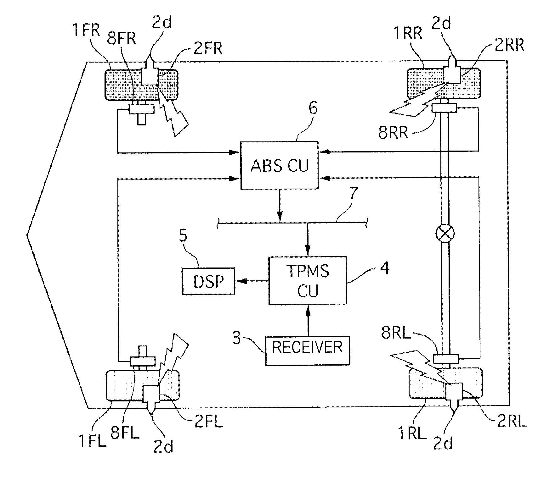
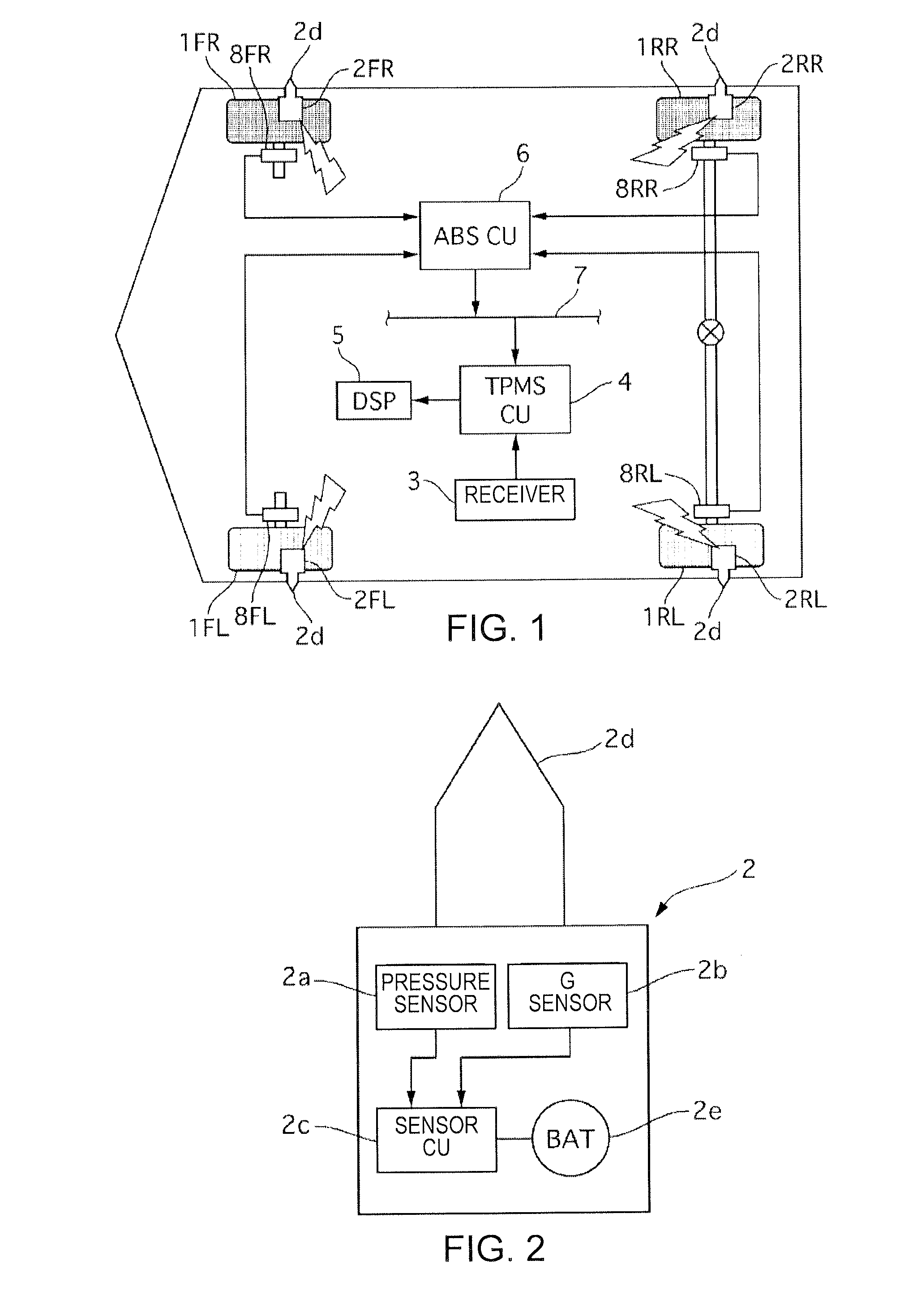
[0032]FIG. 1 is a configuration diagram of a tire air pressure monitor device in the first embodiment. In the drawing each reference numeral is suffixed with FL to indicate the front left wheel, FR to indicate the front right wheel, RL to indicate the rear left wheel and RR to indicate the rear right wheel. In the following explanation, the descriptions of FL, FR, RL, RR will be omitted when a separate description is unnecessary. The tire air pressure monitor device in the first embodiment is provided with a Tire Pressure Monitoring System (TPMS) sensor 2, a receiver 3, a TPMS control unit 4 (TPMSCU), a display 5, and a wheel speed sensor 8. Each of the wheels 1 has a TPMS sensor 2 mounted thereon, while the receiver 3, the TPMSCU 4, the display 5, and the wheel speed sensor 8 are provided on the vehicle body.
[0033]The TPMS sensor 2 is attached at the location of the tire air valve (not shown). FIG. 2 is a configuration diagram of the TPMS sensor 2. The TPMS sensor 2 is equipped wit...
embodiment 2
[0163]FIG. 16 is a control block diagram of a TPMSCU 4 which carries out the wheel position determination control of the second embodiment. The TPMSCU 4 (wheel position determination means) is provided with a rotation position calculation unit 4a, a dispersion calculation unit 4b, a wheel position determination unit 4c, and a memory 4d.
[0164]The rotation position calculation unit 4a, the dispersion calculation unit 4b, the wheel position determination unit 4c, have the same processes as the rotation position calculation unit 11a, the dispersion calculation unit 11b, the wheel position determination unit 11c of the first embodiment illustrated in FIG. 7. In addition in the second embodiment, the wheel position determination unit 4c stores the mapping between the sensors IDs and the wheel positions via a memory update of the memory 4d.
[0165]Wheel Position Determination Control Process
[0166]The flow of the wheel position determination control process of the second embodiment is the s...
embodiment 3
[0176]FIG. 17 is a control block diagram of a TPMSCU 4 which carries out the wheel position determination control of the third embodiment. The TPMSCU 4 (wheel position determination means) is provided with a rotation position calculation unit 4a′, a dispersion calculation unit 4b′, a wheel position determination unit 4c′, and a memory 4d.
[0177]The rotation position calculation unit 4a′, the dispersion calculation unit 4b′, the wheel position determination unit 4c′, have the same processes as the rotation position calculation unit 12a, the dispersion calculation unit 12b, the wheel position determination unit 12c of the first embodiment illustrated in FIG. 7. In addition, in the third embodiment, the wheel position determination unit 4c′ stores the mapping between the sensors IDs and the wheel positions via a memory update of the memory 4d.
[0178]Wheel Position Determination Control Process
[0179]The flow of the wheel position determination control process of the third embodiment is ...
PUM
 Abstract
Description
Claims
Application Information