Tube Fitting Assembly

a technology of fittings and tubes, applied in the field of sealing of fittings, can solve the problems of less than adequate sealing, difficult grip of heavy wall tubing, and more difficult plastic deformation of tubing, and achieve the effect of high performance characteristics

Active Publication Date: 2014-06-26
RIETH PATRICK
View PDF1 Cites 0 Cited by
  • Summary
  • Abstract
  • Description
  • Claims
  • Application Information

AI Technical Summary

Benefits of technology

[0008]It is, therefore, an object of the present invention to provide a ferrule seal assembly that meets high performance characteristics without compromising overall fitting integrity and leak-proof performance.
[0013]The first tube fitting member can be a valve component, a conduit, a manifold or any other device. The second tube fitting member is an externally threaded nut that partially fits into the bore of the first tubing member when pulled up. The tube gripping member is a single ferrule with sufficient plasticity allowing the front end of it to be deformed while being fitted into the notch. The flexing ability of the ferrule allows a partial bending of the ferrule sealing portion, which moves into a sealing contact with the tube end.

Problems solved by technology

Such heavy wall tubing is difficult to grip because it is not only hard but it is also resistive to deformation.
Such physical characteristics make it more difficult to deform the tubing plastically so as to achieve a desired tube grip.
In many known fitting assemblies, the resulting seal is less than adequate, requiring one or more elastomeric seals to prevent leakage of the liquid or gas.

Method used


Image

  • Tube Fitting Assembly
  • Tube Fitting Assembly
  • Tube Fitting Assembly

Examples


Embodiment Construction

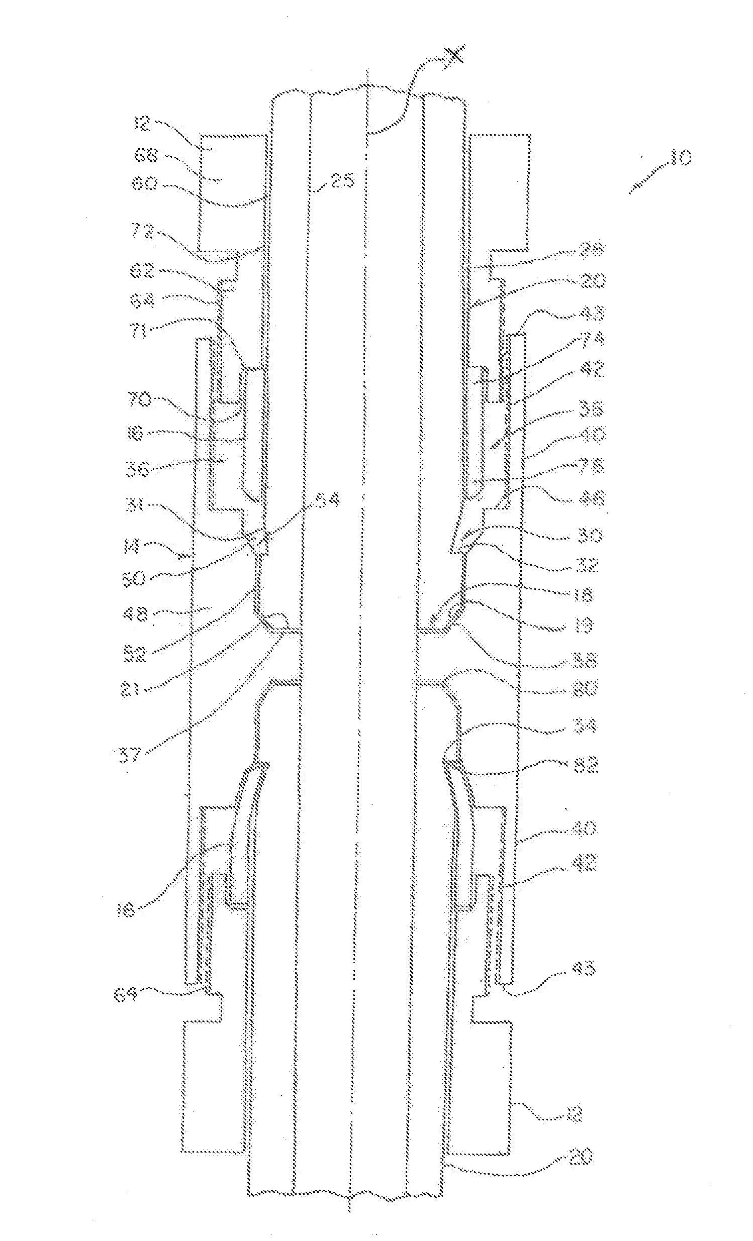
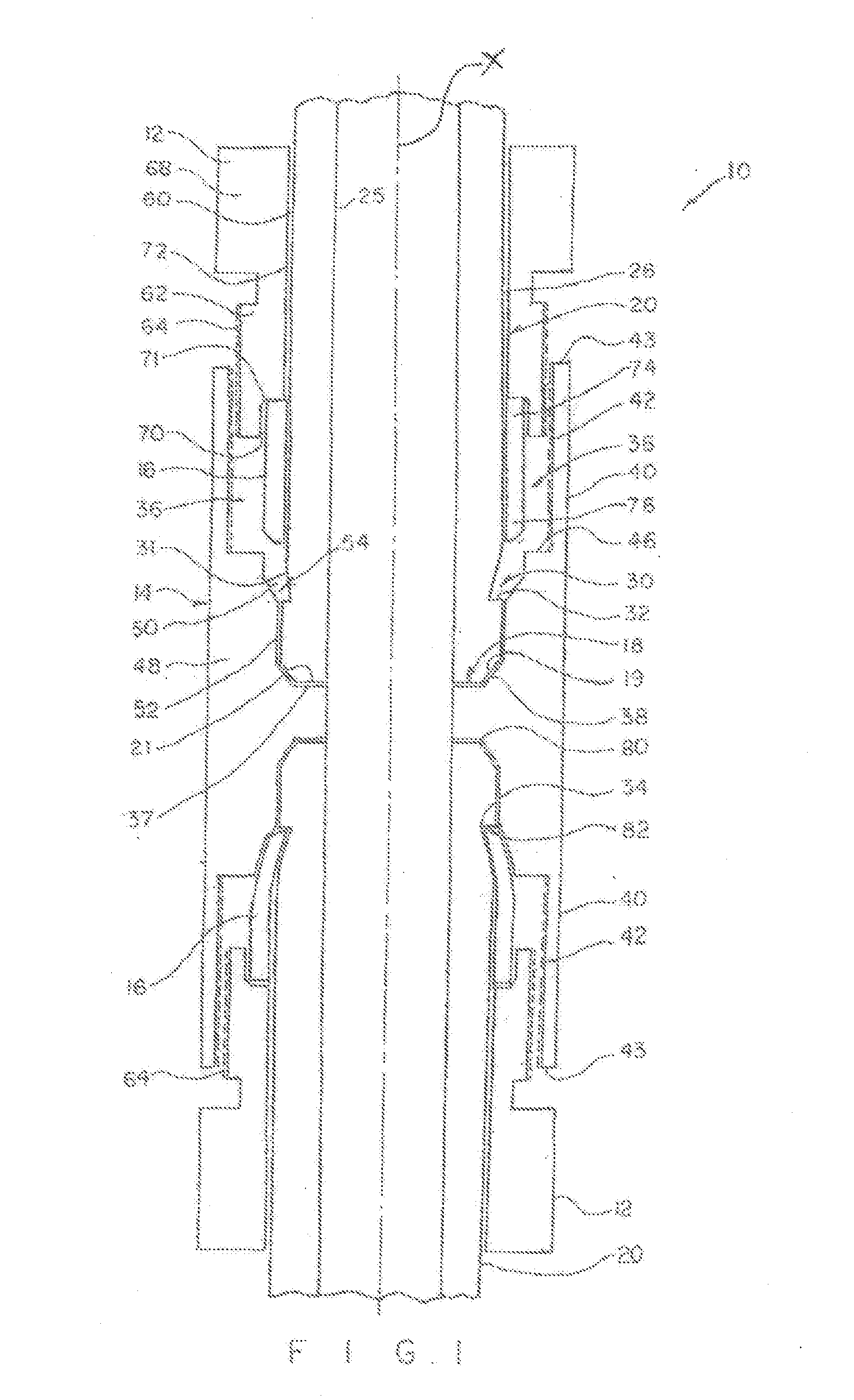
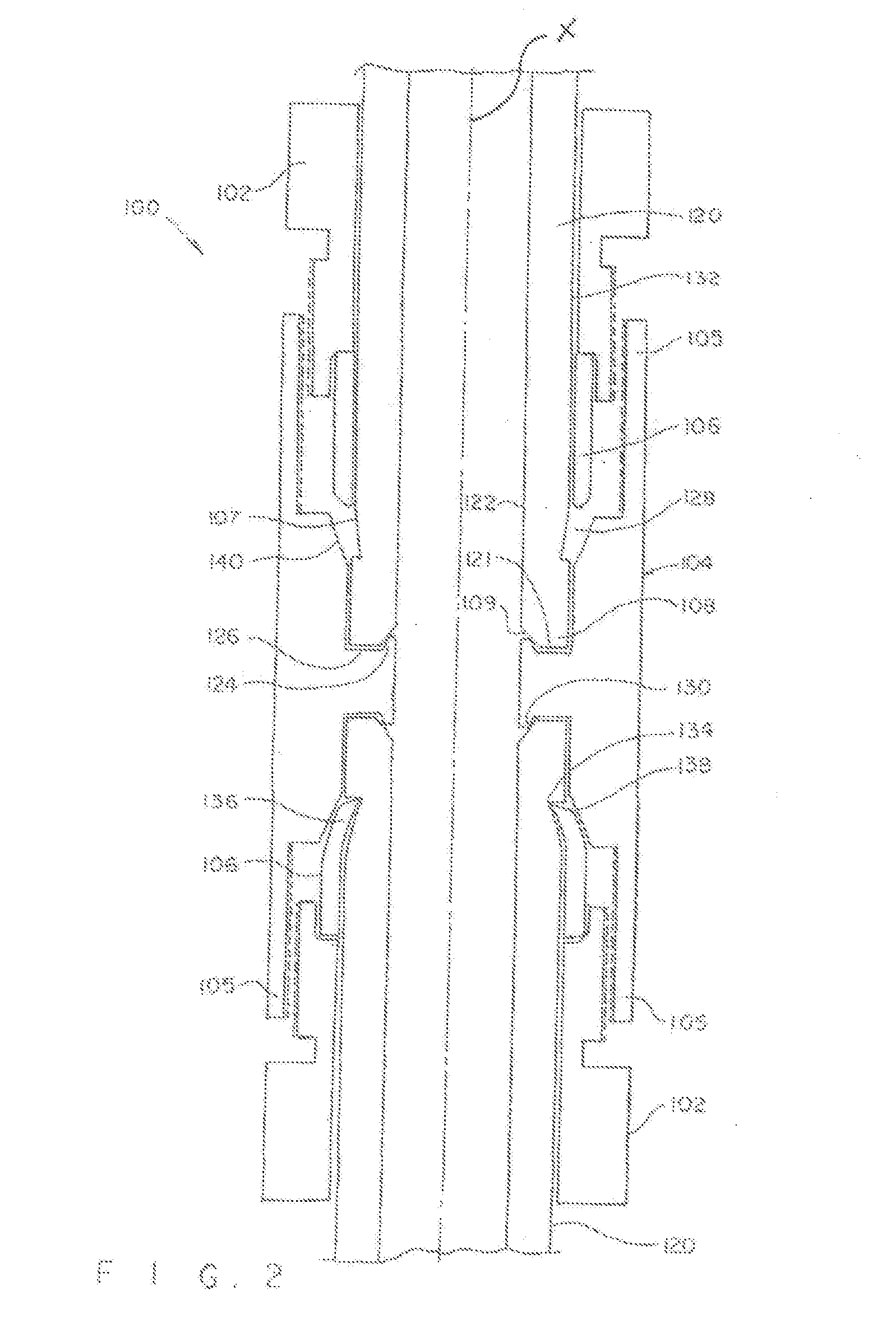
[0018]Turning now to the drawings in more detail, numeral 10 designates the ferrule seal assembly of the present invention. The assembly forms a tube fitting, which comprises a male threaded nut 12, a female threaded body 14 and a tube gripping member, or ferrule 16. The body 14 forms a first tube fitting member, and the nut 12 forms the second tube fitting member. It will be understood that the body 14 does not have to be a separate component but may be attached to or otherwise integral to another device, for instance a valve body, manifold or other components. In one aspect of the invention, the assembly also comprises a specially designed tube with an external notch for receiving the ring-shaped ferrule 16 in a sealing engagement with the end of a tube, as discussed below.

[0019]The assembly 10 is configured for mounting on an end 18 of a tube 20. In the embodiment of FIG. 1, the end 18 of the tube 20 has a frustoconical configuration with an angled surface 19 and a straight trans...


PUM

PropertyMeasurementUnit
distanceaaaaaaaaaa
lengthaaaaaaaaaa
pressureaaaaaaaaaa

Abstract

A tube fitting for sealing an end of a tube uses a notch formed in the exterior surface of the tube as a sealing seat. An internally threaded body is configured to receive an externally threaded end of a nut, while the body and the nut are mounted in a surrounding relationship to the tube end. A ferrule mounted between the nut and the tube is forced to plastically deform and move into the notch to thereby seal the tube end.

Description

CROSS-REFERENCE TO RELATED APPLICATIONS[0001]This application is a continuation of my co-pending application Ser. No. 13 / 068,391 filed on May 10, 2011 and entitled “Tube Fitting Assembly” the full disclosure of which is incorporated by reference herein and priority of which is hereby claimed.BACKGROUND OF THE INVENTION[0002]This invention relates generally to the sealing of fittings about tubes and more particularly, though not exclusively, to the sealing of tubing using a single tube gripping member, such as a ferrule.[0003]Tube fittings are used to join or connect a tube end to another member, whether that other member be another tube end or a device in fluid communication with the tube end. Generally, tube fittings are designed to withstand operational conditions of the environment where the tube is located, such as pressure, vacuum, pull-out pressure, temperature, pulsation and / or vibration. Ideally, a tube fitting grips the tube end so as to prevent loss of seal between the tub...

Claims


Application Information

Patent Timeline
Patent Type & Authority Applications(United States)
IPC IPC(8): F16L19/06
CPCF16L19/065F16L19/06F16L19/061B25B27/06B25B27/10B25B27/023Y10T29/49948Y10T29/53952Y10T29/53848Y10T29/53843Y10T29/49947Y10T29/49908Y10T29/49904Y10T29/49938Y10T29/49909Y10T29/49927Y10T29/53987E05Y2900/50
Inventor RIETH, PATRICK
Owner RIETH PATRICK
Why Eureka
Try Eureka