
Magnetic field sensor and method of fabricating a magnetic field sensor having a plurality of vertical hall elements arranged in at least a portion of a polygonal shape

a magnetic field sensor and polygonal shape technology, applied in galvano-magnetic devices, instruments, solid-state devices, etc., can solve the problems of angular resolution, substantial amount of time required to generate all of the output signals of the cvh sensing element, and inability to determine the direction of the magnetic field in a substantial amount of tim

Active Publication Date: 2014-06-26
ALLEGRO MICROSYSTEMS INC
View PDF0 Cites 28 Cited by
  • Summary
  • Abstract
  • Description
  • Claims
  • Application Information

AI Technical Summary

Benefits of technology

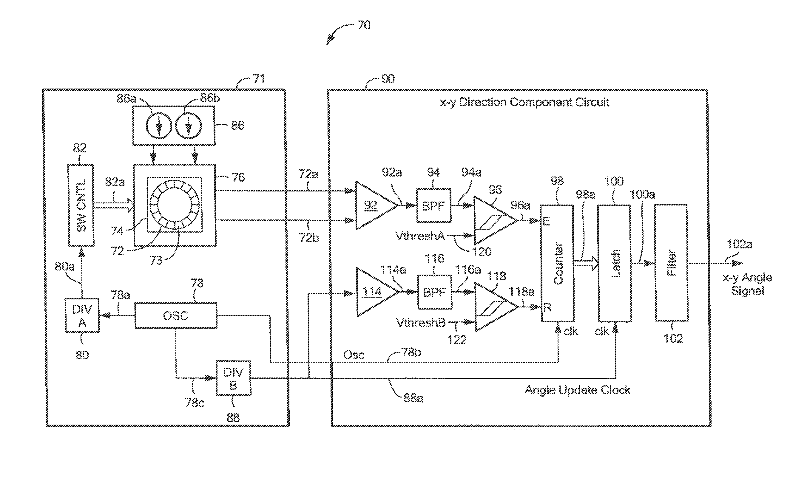
The present invention provides a magnetic field sensor that can generate an output signal more quickly than a conventional CVH sensing element. The sensor includes a semiconductor substrate with a planar surface and a plurality of magnetic field sensing elements disposed on the planar surface. Each sensing element has a respective plurality of primary vertical Hall elements and a plurality of secondary vertical Hall elements. The primary vertical Hall elements are arranged in a pattern representative of at least a portion of a polygonal shape. The sensor also includes an electronic circuit coupled to each sensing element and a plurality of magnetic field sensing elements may include magnetoresistance elements. The technical effect of the invention is to provide a magnetic field sensor with improved accuracy and faster response time for detecting the angle of a magnetic field.

Problems solved by technology

Also conventionally, output signals from the vertical Hall elements of a CVH sensing element are generated sequentially, resulting in a substantial amount of time necessary to generate all of the output signals from the CVH sensing element.
Thus, determination of the direction of the magnetic field can take a substantial amount of time.
Furthermore, the magnetic field sensor may provide an angular resolution that is too low (too large an angle step size).

Method used


Image

  • Magnetic field sensor and method of fabricating a magnetic field sensor having a plurality of vertical hall elements arranged in at least a portion of a polygonal shape
  • Magnetic field sensor and method of fabricating a magnetic field sensor having a plurality of vertical hall elements arranged in at least a portion of a polygonal shape
  • Magnetic field sensor and method of fabricating a magnetic field sensor having a plurality of vertical hall elements arranged in at least a portion of a polygonal shape

Examples


Embodiment Construction

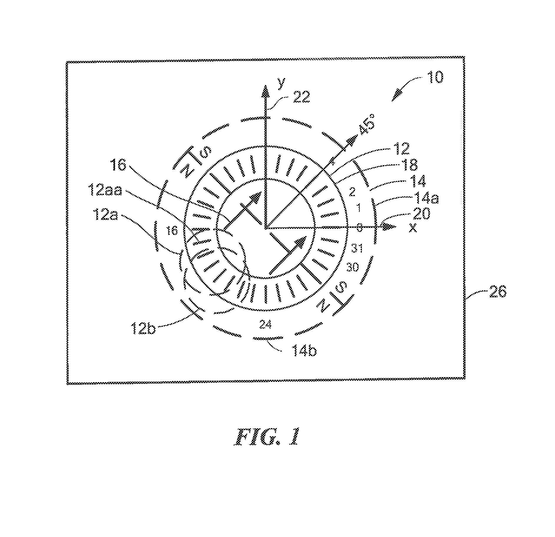
[0033]Before describing the present invention, some introductory concepts and terminology are explained. As used herein, the term “magnetic field sensing element” is used to describe a variety of electronic elements that can sense a magnetic field. The magnetic field sensing elements can be, but are not limited to, Hall Effect elements, magnetoresistance elements, or magnetotransistors. As is known, there are different types of Hall Effect elements, for example, a planar Hall element, a vertical Hall element, and a circular Hall element. As is also known, there are different types of magnetoresistance elements, for example, a giant magnetoresistance (GMR) element, an anisotropic magnetoresistance element (AMR), a tunneling magnetoresistance (TMR) element, an Indium antimonide (InSb) sensor, and a magnetic tunnel junction (MTJ).

[0034]As used herein, the term “sensor” is used to describe a circuit or assembly that includes a sensing element and other components. In particular, as used...


PUM


Abstract

A magnetic field sensor has a plurality of vertical Hall elements arranged in at least a portion of a polygonal shape. The magnetic field sensor includes an electronic circuit to process signals generated by the plurality of vertical Hall elements to identify a direction of a magnetic field. A corresponding method of fabricating the magnetic field sensor is also described.

Description

CROSS REFERENCE TO RELATED APPLICATIONS[0001]Not Applicable.STATEMENT REGARDING FEDERALLY SPONSORED RESEARCH[0002]Not Applicable.FIELD OF THE INVENTION[0003]This invention relates generally to magnetic field sensors and related fabrication techniques, and, more particularly, to a magnetic field sensor and corresponding fabrication technique having a plurality of vertical Hall elements arranged in at least a portion of a polygonal pattern and also having an electronic circuit coupled to the plurality of vertical Hall elements.BACKGROUND OF THE INVENTION[0004]Planar Hall elements and vertical Hall elements are known types of magnetic field sensing elements that can be used in magnetic field sensors. A planar Hall element tends to be responsive to magnetic field perpendicular to a surface of a substrate on which the planar Hall element is formed. A vertical Hall element tends to be responsive to magnetic field parallel to a surface of a substrate on which the vertical Hall element is f...

Claims


Application Information

Patent Timeline
Patent Type & Authority Applications(United States)
IPC IPC(8): G01B7/30H01L29/82H10N52/00
CPCG01R33/0023H01L29/82G01R33/077H01L43/065
Inventor FOLETTO, ANDREAFRIEDRICH, ANDREAS P.YOAKIM, NICOLAS
Owner ALLEGRO MICROSYSTEMS INC
Learn More