Shark Fin Type Car Antenna Assembly

Inactive Publication Date: 2014-06-26
QUANYI ELECTRONICS
View PDF5 Cites 51 Cited by
  • Summary
  • Abstract
  • Description
  • Claims
  • Application Information

AI Technical Summary

Benefits of technology

[0007]According to the primary advantage of the present invention, the height of the antenna elements is increased gradually from the front end toward the rear end of the antenna unit, while the antenna elements have a constant spacing to produce an enough bandwidth so that the bandwidth of the antenna elements is increased so as to increase the receiving effect of the AM and FM signals and to reach the optimum gain effect of the antenna elements.
[0008]Further benefits and advantages of the present invention will become apparent after a careful

Problems solved by technology

However, the receiving rod 110 of the car antenna 11 protrudes outward from the top of the car 1 so that the receiving rod 110 of the car antenna 11 is easily disturbed by an air pressure or drag when the car 1 is driven at a higher speed, thereby

Method used


Image

  • Shark Fin Type Car Antenna Assembly
  • Shark Fin Type Car Antenna Assembly
  • Shark Fin Type Car Antenna Assembly

Examples


Example

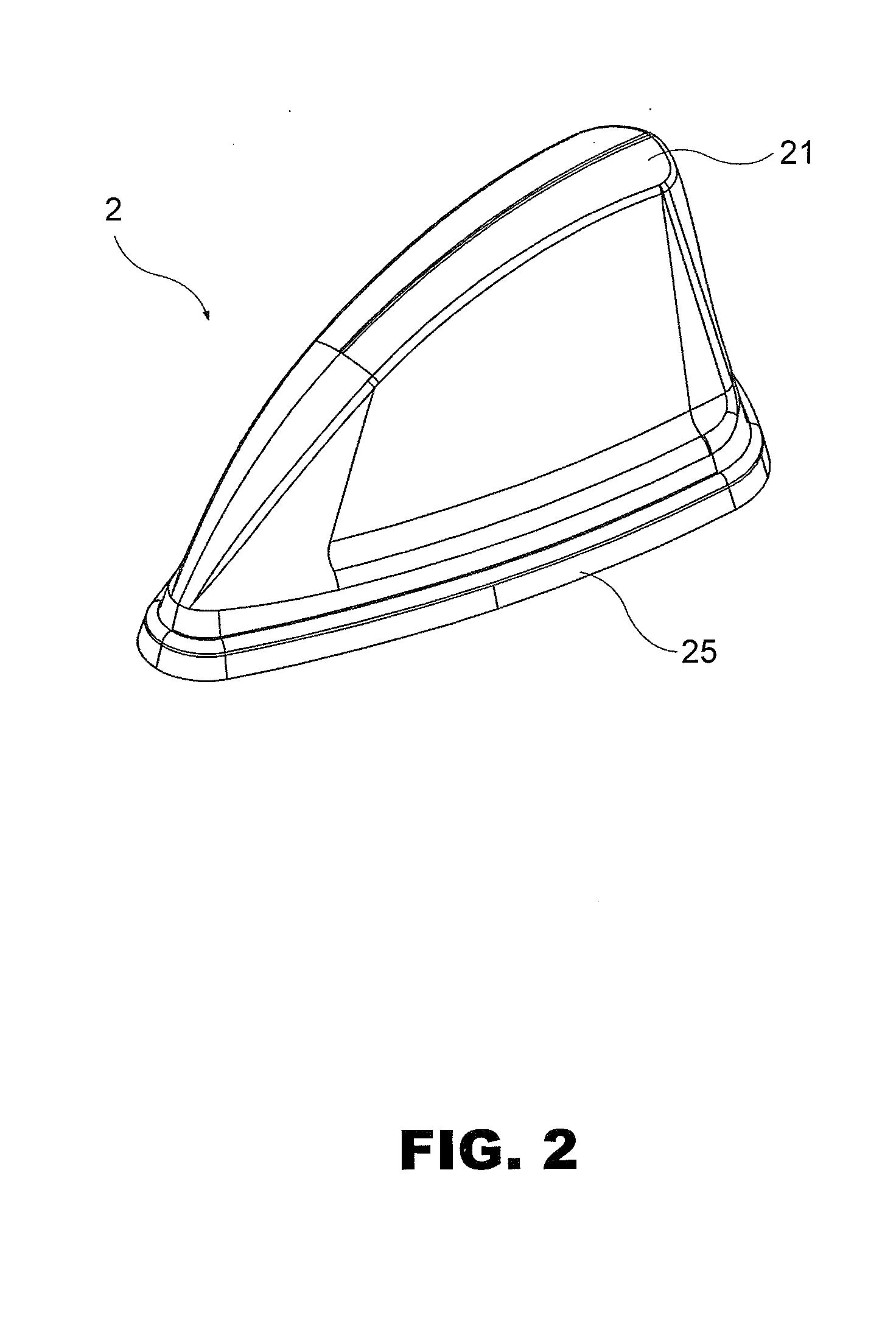
[0020]Referring to the drawings and initially to FIGS. 2 and 3, a shark fin type car antenna assembly 2 in accordance with the preferred embodiment of the present invention comprises an outer cover 21, an antenna unit 22, a fixing seat 23, a locking bar 232, a control board 24, a navigation device 240, and a base 25. The base 25 has a tapered shape and has a width that is increased gradually from the front end of the base 25 toward the rear end of the base 25. The base 25 has an interior provided with a first receiving space 251 to receive the control board 24 and a second receiving space 252 to receive the navigation device 240. The fixing seat 23 is located above the base 25. The fixing seat 23 has a hollow inside and has two opposite sides each provided with a plurality of retaining grooves 231 for mounting and positioning the antenna unit 22. The locking bar 232 is locked onto the fixing seat 23 and presses the antenna unit 22 to lock the antenna unit 22 onto the fixing seat 23....


PUM


Abstract

A car antenna assembly includes an outer cover, an antenna unit, a fixing seat, a locking bar, a control board, and a base. The antenna unit is made of a metallic strip which is bent freely to form a plurality of antenna elements which are connected successively. The outer cover covers the antenna unit and the fixing seat. Thus, the height of the antenna elements is increased gradually from the front end toward the rear end of the antenna unit, while the antenna elements have a constant spacing so that the bandwidth of the antenna elements is increased so as to increase the receiving effect of the AM and FM signals. The car antenna assembly has a shark fin shape to reduce the air drag and air shear noise.

Description

BACKGROUND OF THE INVENTION[0001]1. Field of the Invention[0002]The present invention relates to an antenna assembly and, more particularly, to a shark fin type car antenna assembly.[0003]2. Description of the Related Art[0004]A conventional car antenna 11 in accordance with the prior art shown in FIG. 1 is mounted on the top of a car 1 and comprises a movable receiving rod 110 protruding outward from the top of the car 1. Thus, the car antenna 11 can receive a wireless signal, such as the AM and FM signals, by the receiving rod 110. The receiving rod 110 of the car antenna 11 is pivoted to change its inclined angle so as to adjust the strength of the received wireless signal. However, the receiving rod 110 of the car antenna 11 protrudes outward from the top of the car 1 so that the receiving rod 110 of the car antenna 11 is easily disturbed by an air pressure or drag when the car 1 is driven at a higher speed, thereby decreasing the quality of the received signal. In addition, the...

Claims


Application Information

Patent Timeline
IPC IPC(8): H01Q1/32
CPCH01Q1/3275
Inventor LO, SHAN-GOW
Owner QUANYI ELECTRONICS
Why Eureka
Try Eureka