
Multi-band antenna

Inactive Publication Date: 2014-06-26
COMPAL ELECTRONICS INC
View PDF5 Cites 11 Cited by
  • Summary
  • Abstract
  • Description
  • Claims
  • Application Information

AI Technical Summary

Benefits of technology

The invention is a multi-band antenna that uses the edges of a slot on a metal plate to form a resonant path. A radiation element in the slot is used to excite the resonant path on the metal plate. This reduces the space needed for the antenna while accommodating the mechanical structure and design of the electronic device.

Problems solved by technology

However, although the metallic sense of the exterior design has preferable aesthetics and a more solid appearance, major challenges are presented for antenna design in the electronic device.
However, exterior designs having the metallic sense limits the clearance area needed by the antenna, and thus breakthroughs in the mechanical structure and exterior design of the electronic device remain stagnant.

Method used


Image

  • Multi-band antenna
  • Multi-band antenna
  • Multi-band antenna

Examples


Embodiment Construction

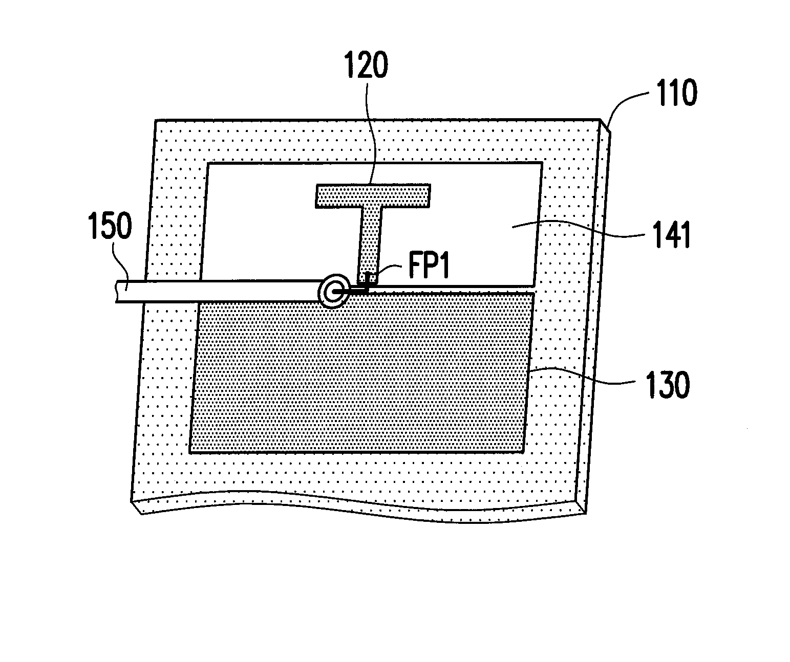
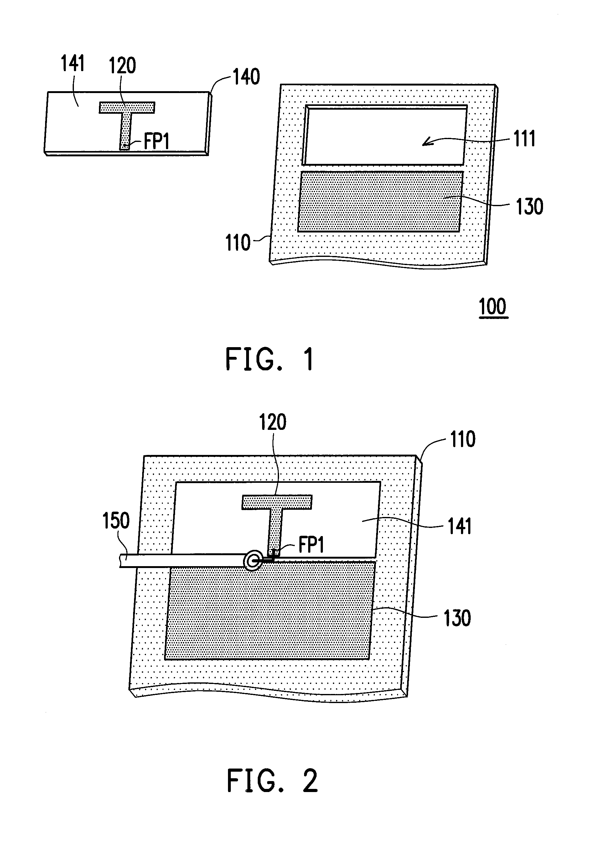
[0021]FIG. 1 is an explosive view of a multi-band antenna according to an embodiment of the invention. With reference to FIG. 1, a multi-band antenna 100 includes a metal plate 110, a radiation element 120, a ground plane 130, and a substrate 140. The metal plate 110 has a slot 111, and the slot 111 penetrates through the metal plate 110. Moreover, the metal plate 110 is electrically connected to the ground plane 130. For example, in the embodiment depicted by FIG. 1, the ground plane 130 is directly adhered on the metal plate 110, such that the metal plate 110 is electrically connected to the ground plane 130.

[0022]In addition, with regards to the overall configuration, the size of the substrate 140 is configured to correspond to the size of the slot 111 of the metal plate 110, such that the substrate 140 may be inserted in the slot 111. Moreover, the radiation element 120 is disposed on a surface 141 of the substrate 140. Accordingly, the radiation element 120 is positioned in the...


PUM


Abstract

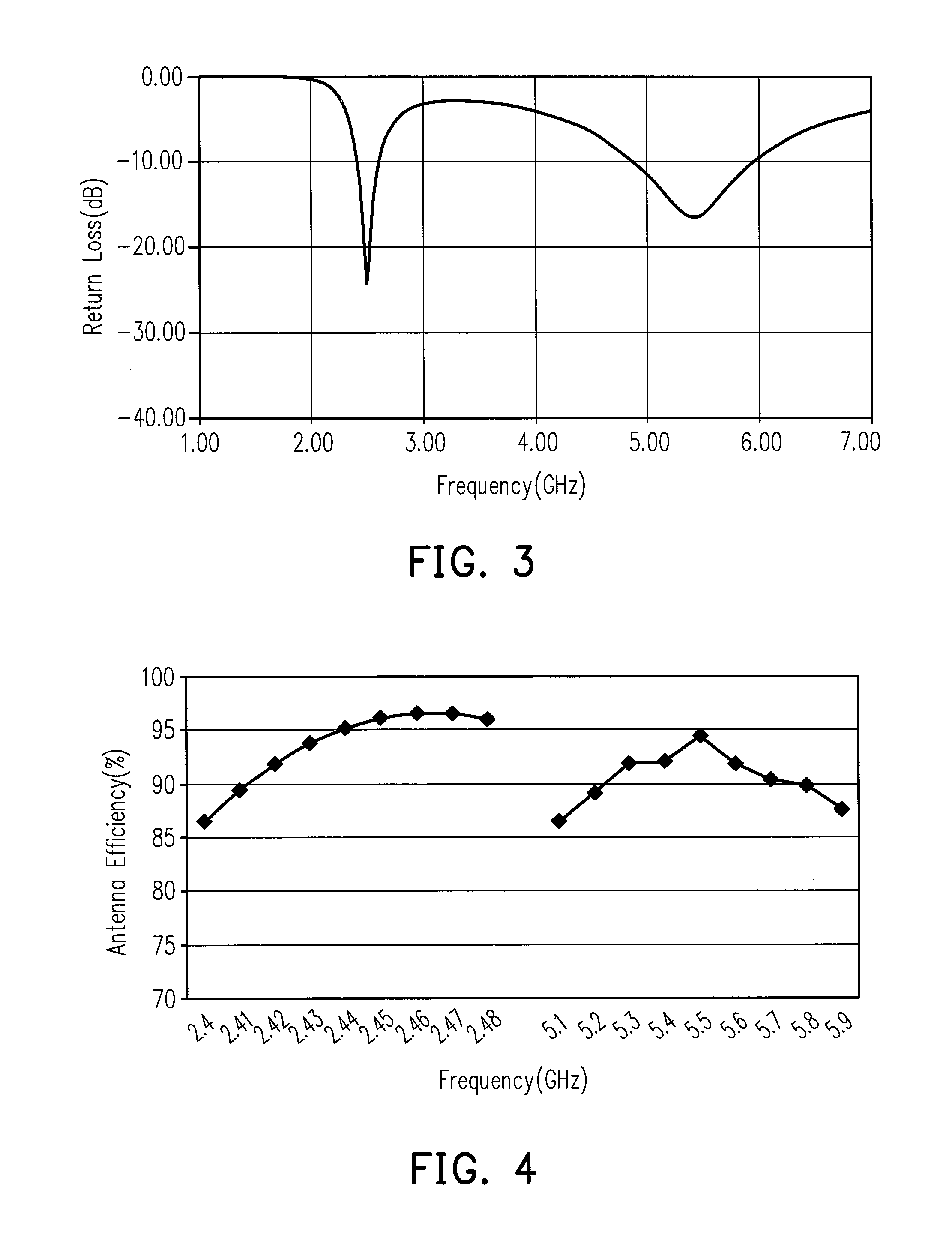
A multi-band antenna including a metal plate and a radiation element is provided. The metal plate is electrically connected to a ground plane and has a slot. A resonant path is formed by the edges of the slot. The radiation element has a feeding point and is located in the slot of the metal plate. A feeding signal from the radiation element is coupled to the metal plate, and the multi-band antenna excites a resonant mode by the resonant path of the metal plate, so as to receive or transmit a first radio frequency signal.

Description

CROSS-REFERENCE TO RELATED APPLICATION[0001]This application claims the priority benefits of U.S. provisional application Ser. No. 61 / 745,806, filed on Dec. 25, 2012. The entirety of the above-mentioned patent applications is hereby incorporated by reference herein and made a part of this specification.BACKGROUND OF THE INVENTION[0002]1. Field of the Invention[0003]The invention relates to an antenna, and more particularly to a multi-band antenna.[0004]2. Description of Related Art[0005]In wireless capable electronic devices nowadays, such as the notebook computer or the tablet computer, not only is the trend towards a thin and light outer appearance, but an exterior design with metal casing or other metallic materials are adopted to attract consumer attention.[0006]However, although the metallic sense of the exterior design has preferable aesthetics and a more solid appearance, major challenges are presented for antenna design in the electronic device. For example, the configuratio...

Claims


Application Information

Patent Timeline
IPC IPC(8): H01Q5/00H01Q13/10H01Q5/10H01Q5/40
CPCH01Q13/10H01Q5/001H01Q9/36H01Q21/30H01Q5/40
Inventor YU, YEN-HAOHWANG, CHIEH-TSAOLIU, SHIH-CHIA
Owner COMPAL ELECTRONICS INC
Learn More