
Satellite antenna and waveguide filter thereof

Active Publication Date: 2014-06-26
WISTRON NEWEB
View PDF7 Cites 8 Cited by
  • Summary
  • Abstract
  • Description
  • Claims
  • Application Information

AI Technical Summary

Benefits of technology

The invention is about a new design for a waveguide filter that allows for a more complex structure without compromising its performance. The filter uses a rib structure that allows for the passage of a junction line without affecting the waveguide. The design also allows for easy manufacturing and mass production of complex filters without sacrificing their electromagnetic performance.

Problems solved by technology

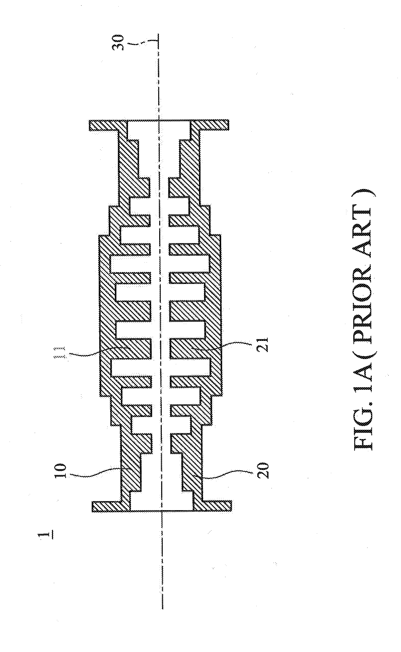
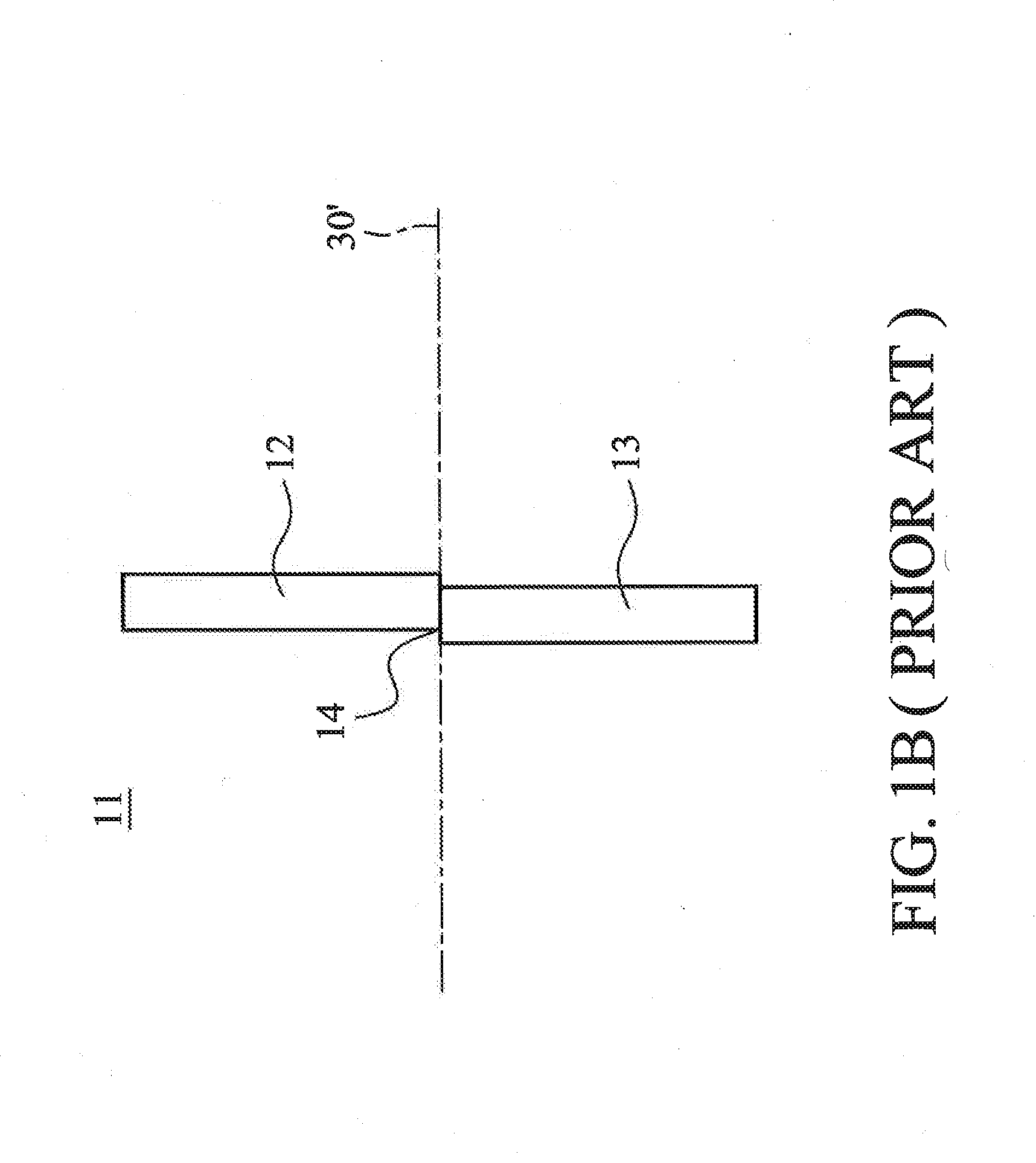
However, if the junction line 30 passes through the ribs, the surfaces of the ribs are uneven due to manufacturing discrepancies, and noise is therefore generated.

Method used


Image

  • Satellite antenna and waveguide filter thereof
  • Satellite antenna and waveguide filter thereof
  • Satellite antenna and waveguide filter thereof

Examples


Embodiment Construction

[0019]The following description is of the best-contemplated mode of carrying out the invention. This description is made for the purpose of illustrating the general principles of the invention and should not be taken in a limiting sense. The scope of the invention is best determined by reference to the appended claims.

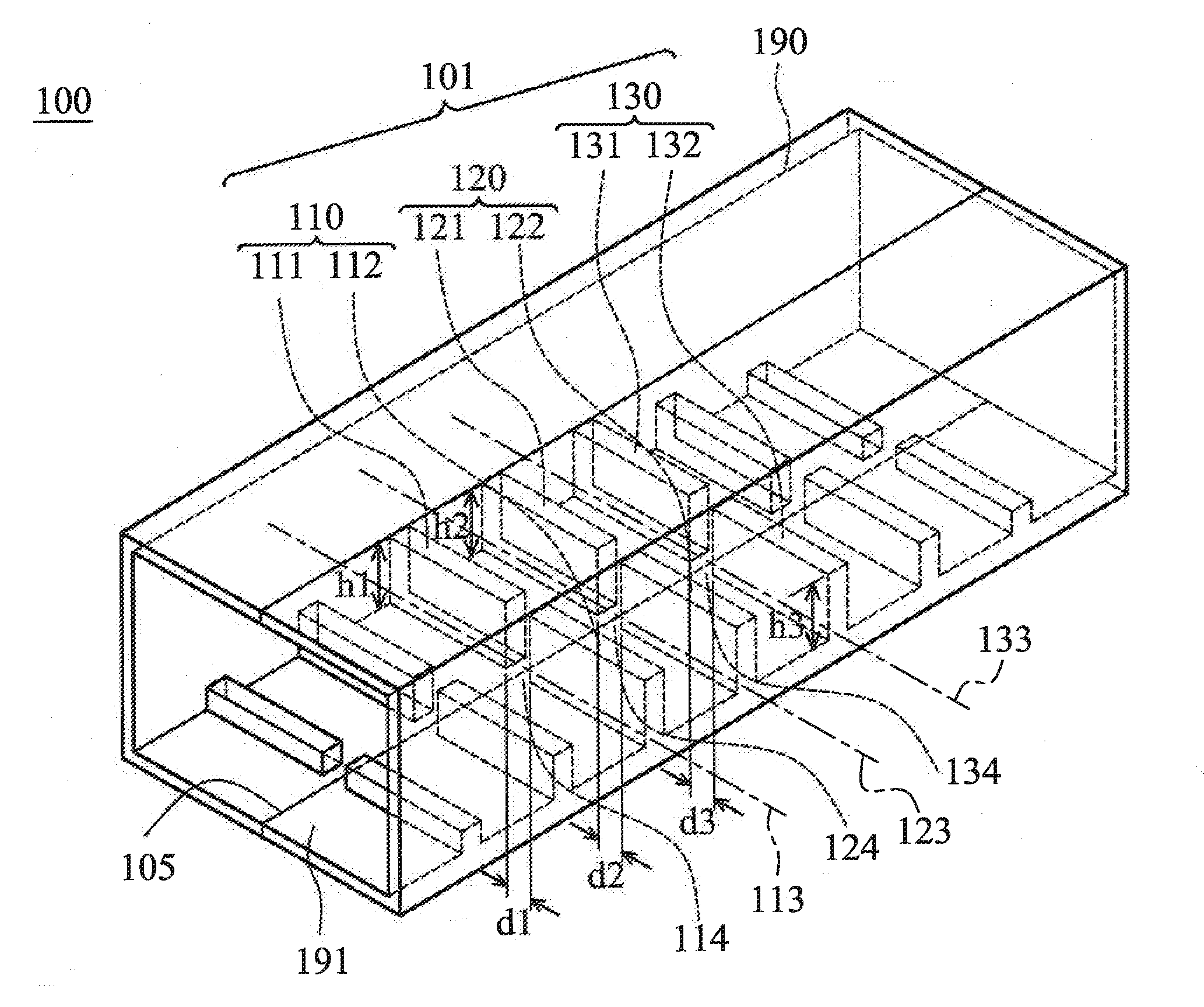
[0020]FIG. 2A shows a waveguide filter 100 of an embodiment of the invention, comprising a pipe 190 and a first rib structure 101. The first rib structure 101 comprises a first rib 110, a second rib 120 and a third rib 130. The pipe 190 comprises a first inner wall 191.

[0021]The first rib 110 is disposed in the pipe 190 and formed on the first inner wall 191. The first rib 110 comprises a first section 111 and a second section 112, wherein the first section 111 and the second section 112 extend on a first straight line 113, and are perpendicular to the first inner wall 191. A first gap 114 is formed between the first section 111 and the second section 112, and a first ...


PUM


Abstract

A waveguide filter is provided. The waveguide filter includes a pipe and a first rib structure. The pipe includes a first inner wall. The first rib structure includes a first rib. The first rib is disposed in the pipe and formed on the first inner wall. The first rib includes a first section and a second section, wherein the first section and the second section extend on a first straight line and are perpendicular to the first inner wall, and a first gap is formed between the first section and the second section, and a first gap distance of the first gap is between 0.1 to 1.2 mm.

Description

CROSS REFERENCE TO RELATED APPLICATIONS[0001]This Application claims priority of Taiwan Patent Application No. 101225024, filed on Dec. 25, 2012, the entirety of which is incorporated by reference herein.BACKGROUND OF THE INVENTION[0002]1. Field of the Invention[0003]The present invention relates to a waveguide filter, and in particular, relates to a waveguide filter utilized in a satellite antenna.[0004]2. Description of the Related Art[0005]Conventional waveguide filters, such as Tapered Chebyshev function stub filters and Tapered Zolotarev function stub filters, have large dimensions due to impedance matching requirements.[0006]The waveguide filters are commonly formed by molding. FIG. 1A shows a conventional waveguide filter 1, which has an upper structure 10 and a lower structure 20. The upper structure 10 has an upper rib 11, and the lower structure 20 has a lower rib 21. In the manufacturing process of the waveguide filter 1, the upper structure 10 and the lower structure 20 ...

Claims


Application Information

Patent Timeline
IPC IPC(8): H01P1/201H01Q13/00
CPCH01Q13/00H01P1/201H01P1/207H01P1/211
Inventor KUO, SHUN-CHUNGHUANG, CHANG-HSIU
Owner WISTRON NEWEB
Learn More