Rotor core assembly

a rotor core and assembly technology, applied in the direction of lamination, dynamo-electric machines, electrical apparatus, etc., can solve the problems of rotor imbalance, magnet fracture, and many magnets are relatively brittle and will fracture, and achieve the effects of reducing the cost and weight of the rotor core assembly, and relatively quick cure in atmospheric moistur

Active Publication Date: 2014-07-03
DYSON TECH LTD
View PDF13 Cites 9 Cited by
  • Summary
  • Abstract
  • Description
  • Claims
  • Application Information

AI Technical Summary

Benefits of technology

[0007]The adhesive provides a medium through which tensile stresses acting on the magnet may be transferred to the sleeve. Accordingly, excessive strain and fracture of the magnet may be avoided.
[0021]The method may comprise preventing adhesive from entering the bore in the magnet. This then ensures that a clean surface is maintained for securing the rotor core assembly to a shaft.

Problems solved by technology

Many magnets are relatively brittle and will fracture if subjected to excessive tensile stress.
As a result, the magnet may fracture.
Although the sleeve may prevent the magnet from breaking apart, the fracture may bring about a slight mass redistribution of the magnet, resulting in rotor imbalance.
However, there are several disadvantages with this method of securement.
First, owing to tolerances and other imperfections in the surfaces of the magnet and the sleeve, there may be locations at which the adhesive does not extend fully between the magnet and the sleeve.
Consequently, there will be locations at which stresses are not transferred from the magnet to the sleeve, which may result in magnet fracture.
Second, the sleeve is poorly constrained relative to the shaft.
As a result, the position of the sleeve may drift with use of the rotor due to adhesive creep.
Any movement in the sleeve will introduce a rotor imbalance.
Third, tolerances in the magnet and the sleeve may mean that an excessive amount of adhesive must be applied to the surfaces in order to achieve a good adhesive join.
Consequently, the method is particularly wasteful in terms of adhesive.
Fourth, owing to the relatively high viscosity of the adhesive, cleaning excess adhesive from the rotor is generally difficult.

Method used


Image

  • Rotor core assembly
  • Rotor core assembly
  • Rotor core assembly

Examples


Embodiment Construction

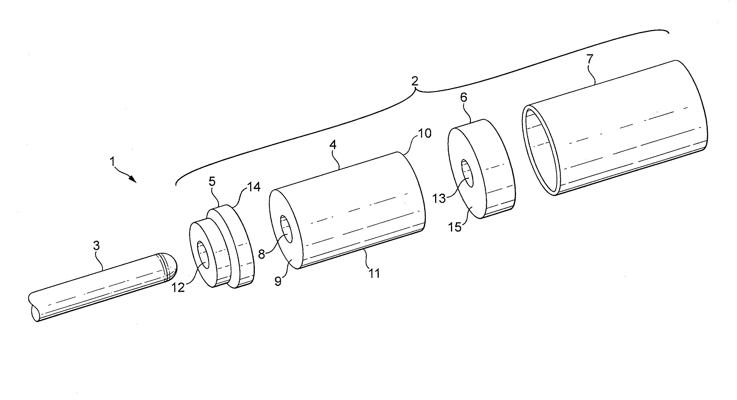
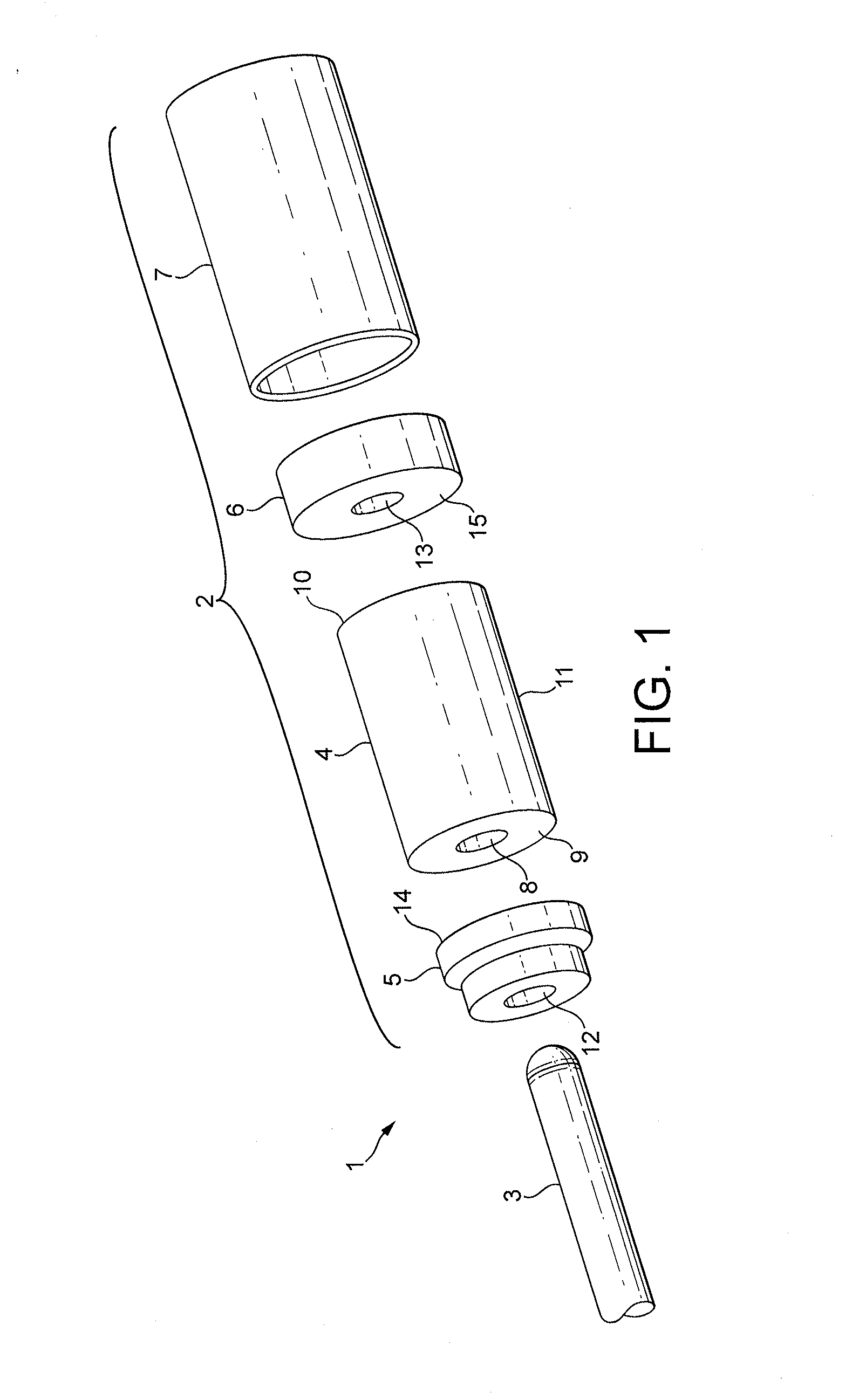
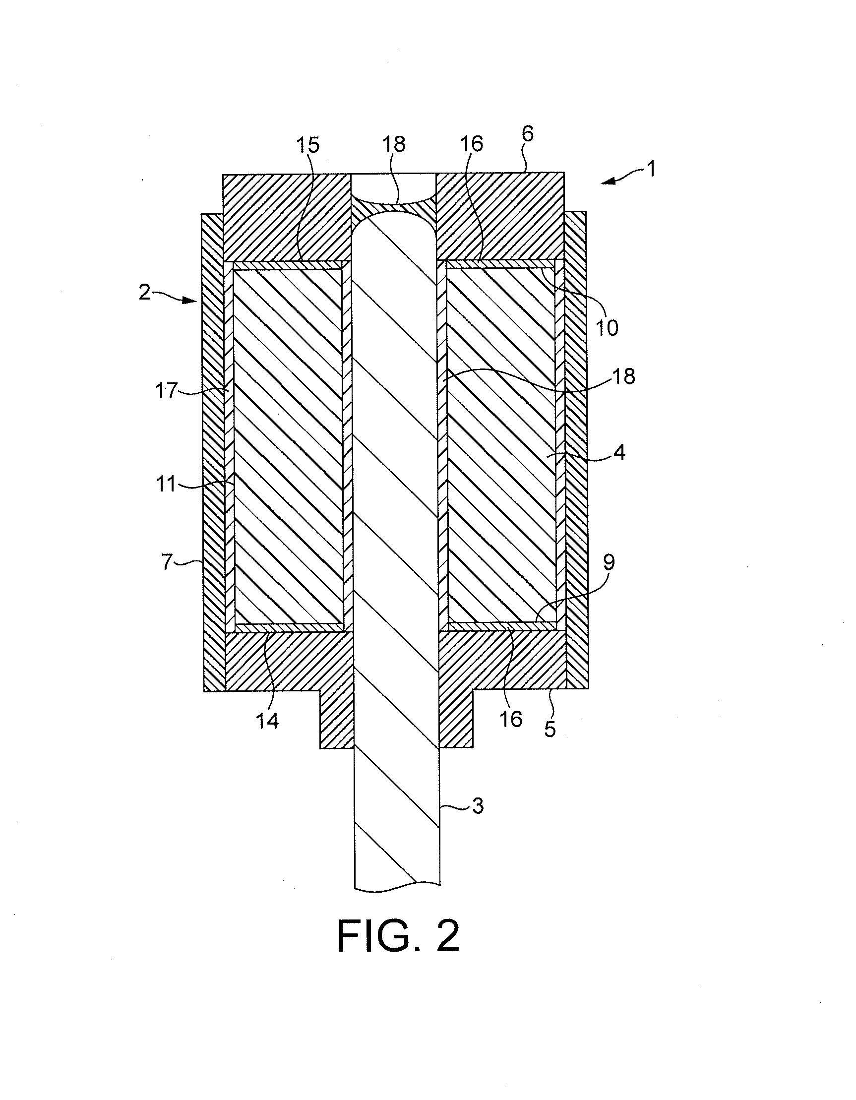
[0033]The rotor 1 of FIGS. 1 and 2 comprises a rotor core assembly 2 secured to a shaft 3.

[0034]The rotor core assembly 2 comprises a permanent magnet 4, a first end cap 5, a second end cap 6, and a sleeve 7.

[0035]The magnet 4 is cylindrical in shape and has a central bore 8 that extends through the magnet 4 from a first end 9 to a second end 10. The bore 8 is sized such that the shaft 3 forms a clearance fit with the magnet 4 when inserted into the bore 8.

[0036]Each end cap 5,6 is made of plastic and has a bore 12,13 formed therethrough. The bore 12,13 in each end cap 5,6 is sized such that the shaft 3 forms an interference fit with the end cap 5,6 when inserted into the bore 12,13. The bore 12,13 in each end cap 5,6 is thus smaller than the bore 8 in the magnet 4. Each end cap 5,6 has a mating face 14,15 that is secured to an end 9,10 of the magnet 4 by an adhesive 16. The end caps 5,6 are secured to the magnet 4 such that the outer diameter of the magnet 4 is aligned concentrical...


PUM

PropertyMeasurementUnit
pressureaaaaaaaaaa
pressureaaaaaaaaaa
adhesiveaaaaaaaaaa

Abstract

A rotor core assembly that includes a magnet, a first end cap located at an end of the magnet, a second end cap located at an opposite end of the magnet, and a sleeve that surrounds the magnet and the end caps. The sleeve forms an interference fit with each of the end caps, and an adhesive is located between the magnet and the sleeve. Additionally, a method of manufacturing the rotor core assembly.

Description

REFERENCE TO RELATED APPLICATIONS[0001]This application is a divisional of U.S. patent application Ser. No. 13 / 212,849, filed Aug. 18, 2011, which claims the priority of United Kingdom Application No. 1014073.9, filed Aug. 24, 2010, and United Kingdom Application No. 1100987.5, filed Jan. 20, 2011, the entire contents of which are incorporated herein by reference.FIELD OF THE INVENTION[0002]The present invention relates to a rotor core assembly for an electrical machine.BACKGROUND OF THE INVENTION[0003]The rotor of an electrical machine may comprise a magnet secured to a shaft. As the rotor rotates, radial forces stress the magnet. Many magnets are relatively brittle and will fracture if subjected to excessive tensile stress. Consequently, a reinforcing sleeve may be provided around the magnet.[0004]Conventional methods of securing a sleeve about a magnet include press-fitting the magnet into the sleeve. However, owing to tolerances in the outer surface of the magnet and the inner s...

Claims


Application Information

Patent Timeline
Patent Type & Authority Applications(United States)
IPC IPC(8): H01F41/02
CPCH01F41/02H02K1/2733H02K15/03H02K15/12Y10T29/49012H02K1/28H02K1/27
Inventor IONS, DAVIDHEYTING, PAUL THEOCHILDE, MATTHEW JOHNJONES, DAVID MICHAEL
Owner DYSON TECH LTD
Why Eureka
Try Eureka