Gas Diffusion Unit

a technology of gas diffusion and gas diffusion layer, which is applied in the field of gas diffusion unit, can solve the problems of difficult mutual alignment of gas diffusion layer, deformation of fuel cell, and deformation of efficiency, and achieve the effects of preventing leakage, improving sealing action, and large-scale production

Active Publication Date: 2009-01-29
CARL FREUDENBERG KG
View PDF10 Cites 2 Cited by
  • Summary
  • Abstract
  • Description
  • Claims
  • Application Information

AI Technical Summary

Benefits of technology

[0015]Adhesive bonding renders possible a modular type of production, in which various seal designs may be combined with various designs of gas diffusion layers. Its flexibility makes it especially suited for a relatively small-volume production. The seals may be injection molded onto the gas diffusion layer. Injection molding is a manufacturing method that is suitable for large-scale production. The process of injection molding onto the gas diffusion layers produces a peripheral seal which completely surrounds a reaction layer configured between the gas diffusion layers, thereby preventing leakage. During the injection molding process, it is advantageous that the sealing material that is injection molded onto the gas diffusion layer penetrates into the gas diffusion layer. The penetration is effected in particular when working with gas diffusion layers made of a nonwoven fabric. The sealing action, as well as the manipulability are again thereby improved.
[0016]The seals may at least have an at least partially peripherally extending sealing bead. The sealing bead may, in particular, have a V-shaped form. A sealing bead improves the sealing action and simplifies the assembly of the membrane-electrode assembly. For the assembly operation, the interconnected gas diffusion layers, together with the membrane configured therebetween, are pressed together between bipolar plates by screw connections. Due to the small contact surface area of the sealing bead, the clamping force is initially small, but intensifies in response to increasing compression. Once the sealing bead is fully compressed, the adjacent planar sealing region engages, and the clamping force increases disproportionally, which may be indicative of a correct clamping force and thus sealing force. An overpressing of the seal due to an excessive clamping force is thereby prevented. Moreover, the sealing bead compensates for tolerances and unevenness of the surface to be sealed.
[0017]The gas diffusion unit may be less than 2 mm thick. This makes it possible to design especially compact fuel cells, in particular for mobile applications or for small electrical devices.
[0018]The seals may at least have an at least partially peripherally extending sealing bead and a peripherally extending recess, the recess being configured adjacently to the sealing bead. The recesses make space available into which the material of the sealing bead may be displaced in response to increasing clamping force. Excessive strains are thereby prevented that could lead to tearing or buckling of the sealing bead. The sealing action is improved.
[0019]The seals may also extend peripherally around the passages provided in the bipolar plates for supplying the reaction and cooling media. Since these regions react very sensitively to any misalignment of the seal during assembly, the invention provides additional advantages in this case. In this manner, the various requirements of fuel cell seals are met cost-effectively by only one sealing element.
[0020]The gas diffusion layer may include a nonwoven fabric. Nonwoven fabrics are inexpensive and form a stable gas diffusion layer. Moreover, the nonwoven fabric forms a good adhesive base for the sealing material, since the material of the seal is able to penetrate into the nonwoven fabric due to the porosity thereof. In this context, the nonwoven fabric is typically carbonized. The gas diffusion layer may feature a porous nonwoven fabric that contains carbon fiber objects or carbon objects. Carbon fibers improve the electrical conductivity of the gas diffusion layer.

Problems solved by technology

Leakage can lead to destruction of the fuel cell, and it degrades the efficiency thereof.
During assembly, it is difficult to mutually align the gas diffusion layers in a way that imperviously seals the contact regions of the gas diffusion layer and the reaction layer, as well as of the gas diffusion layer and bipolar plate.

Method used


Image

  • Gas Diffusion Unit
  • Gas Diffusion Unit
  • Gas Diffusion Unit

Examples


Embodiment Construction

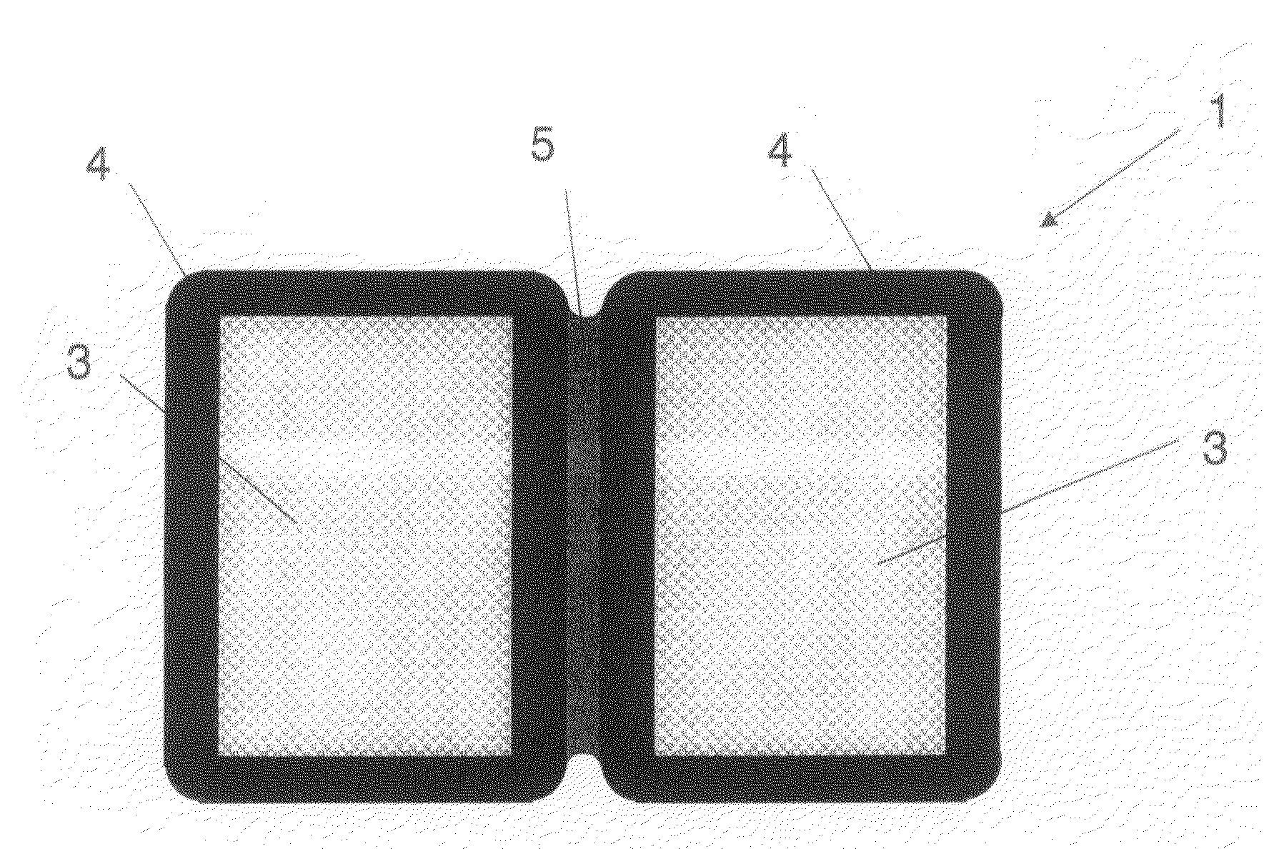
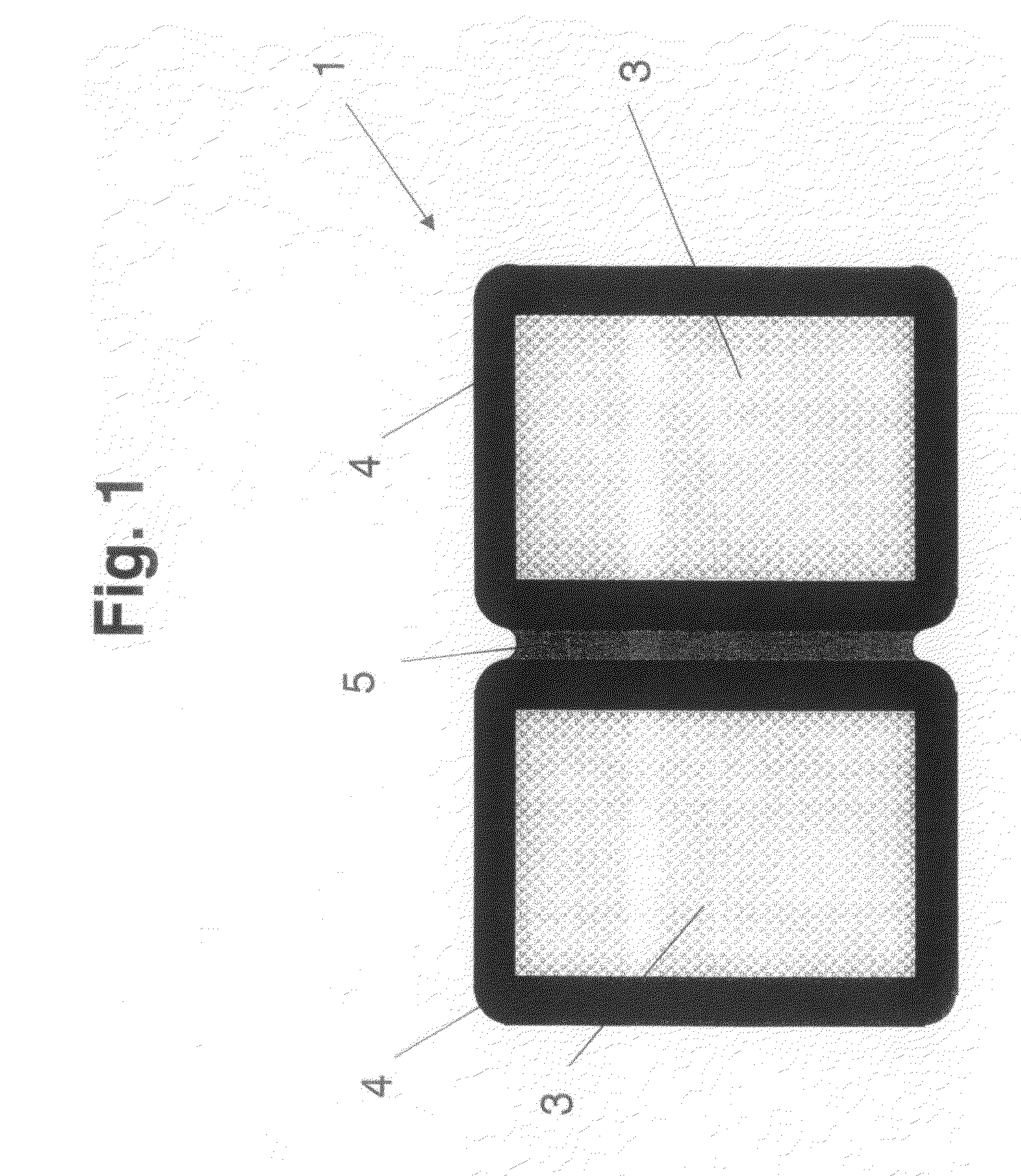
[0031]FIG. 1 shows a gas diffusion unit 1 for a fuel cell 2 composed of two planar gas diffusion layers 3. Gas diffusion layers 3 are made of a carbonized nonwoven fabric, seals 4 being configured at the perimeters of gas diffusion layers 3. In this variant, seals 4 are made of a composition that includes silicon and were affixed to gas diffusion layers 3 by injection molding, the sealing material having penetrated into the pores of the nonwoven fabric. In other variants, the seal may also be made of thermoplastic elastomers, EPDM (ethylene propylene dien monomer), PIB (polyisobutylene), PU (polyurethane), BR (butadiene) or of a blend of these materials, including silicon. Seals 4 of both gas diffusion layers 3 are formed of uniform material and in one piece and, in this variant, are joined together by a connection strip 5. The two gas diffusion layers 3 are joined together by connection strip 5 in an articulated manner.

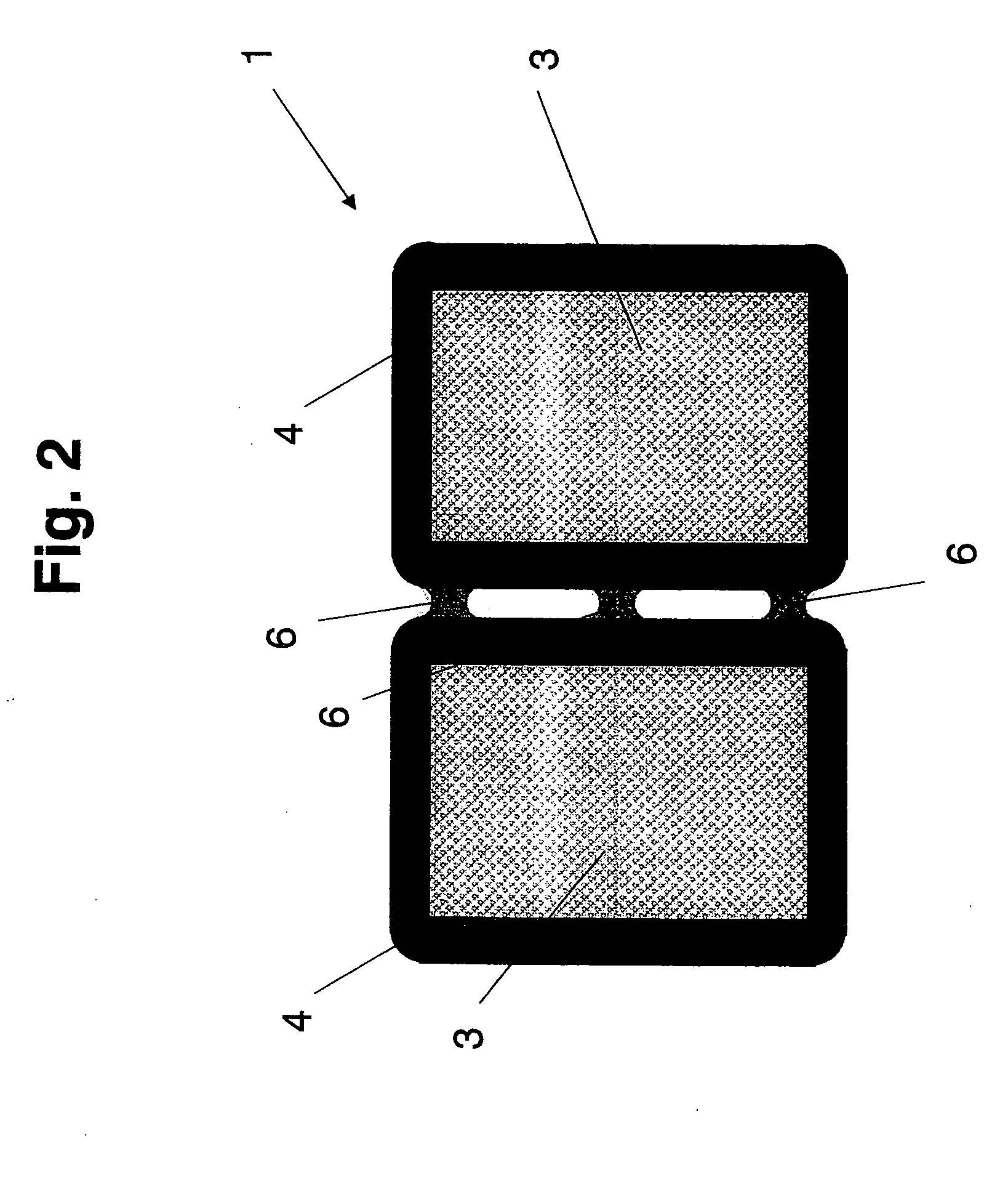
[0032]FIG. 2 shows a gas diffusion unit 1 according to FIG. 1, ...


PUM

PropertyMeasurementUnit
thickaaaaaaaaaa
thicknessaaaaaaaaaa
elasticaaaaaaaaaa

Abstract

A gas diffusion unit (1) for a fuel cell (2), having at least two planar gas diffusion layers (3) on whose edges seals (4) are configured, at least two gas diffusion layers (3) being joined together in an articulated manner.

Description

[0001]The present invention relates to a gas diffusion unit for a fuel cell, having at least two planar gas diffusion layers on whose edges seals are configured.BACKGROUND OF THE INVENTION[0002]Fuel cells are composed of individual, serially interconnected cells. These form what is generally referred to as a stack or cell stack, into which additional cooling components are frequently integrated. In this context, a stack may include up to 500 individual cells. A cell is characterized by a layered structure, one cell being composed of an arrangement made up of two bipolar plates having a gas distribution structure, two gas diffusion layers and of a reaction layer in the form of a catalyzed membrane. Two gas diffusion layers surround the reaction layer and form a membrane-electrode assembly. To prevent leakage, the membrane-electrode assembly or the bipolar plate is provided with a seal. Leakage can lead to destruction of the fuel cell, and it degrades the efficiency thereof. From the ...

Claims


Application Information

Patent Timeline
Patent Type & Authority Applications(United States)
IPC IPC(8): H01M2/08
CPCH01M8/0234H01M8/0273H01M8/0276Y02E60/50H01M8/0286H01M8/0297H01M2008/1095H01M8/0284H01M8/04H01M8/02H01M8/0258
Inventor GERDING, LARS
Owner CARL FREUDENBERG KG
Why Eureka
Try Eureka