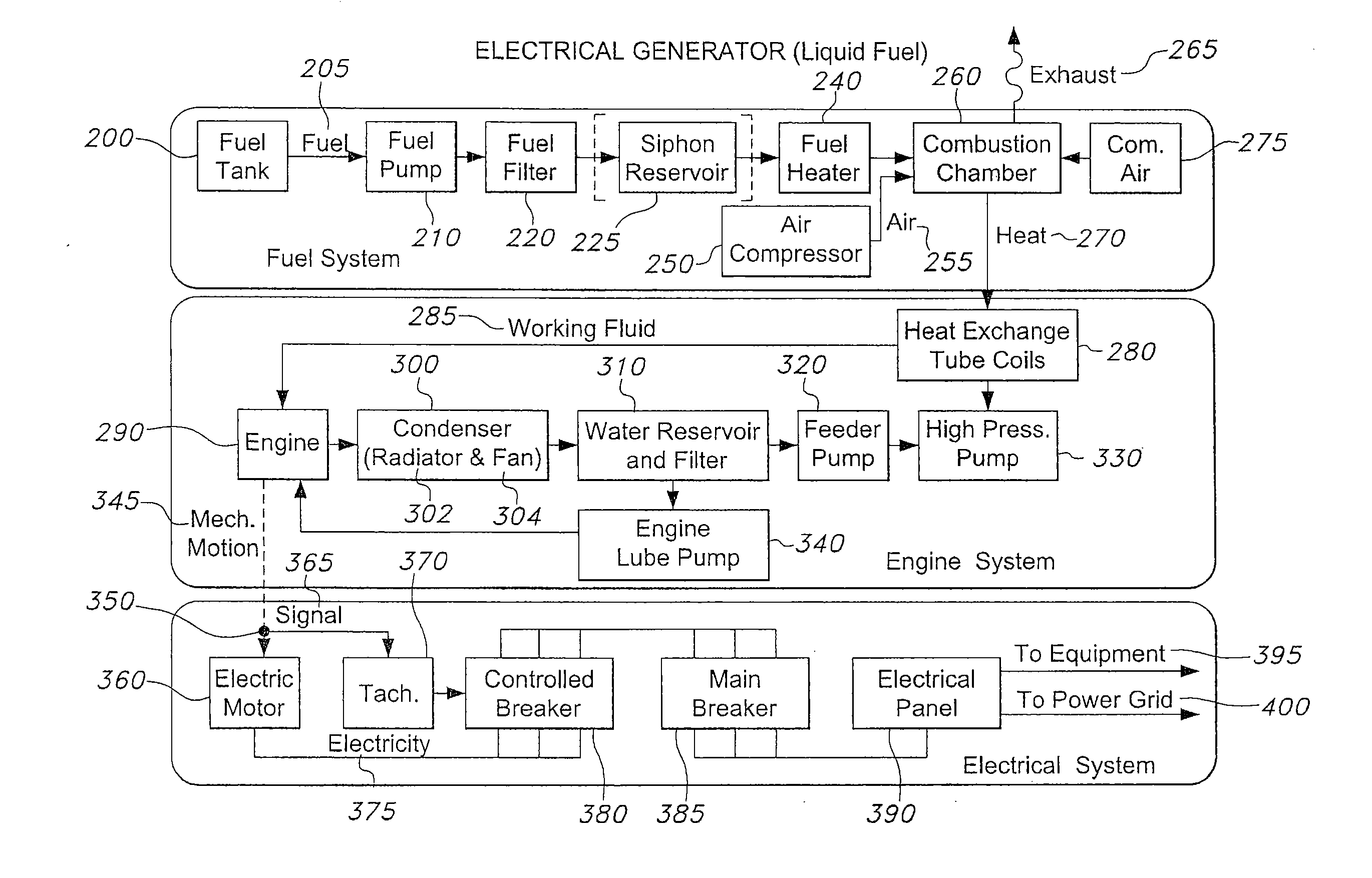
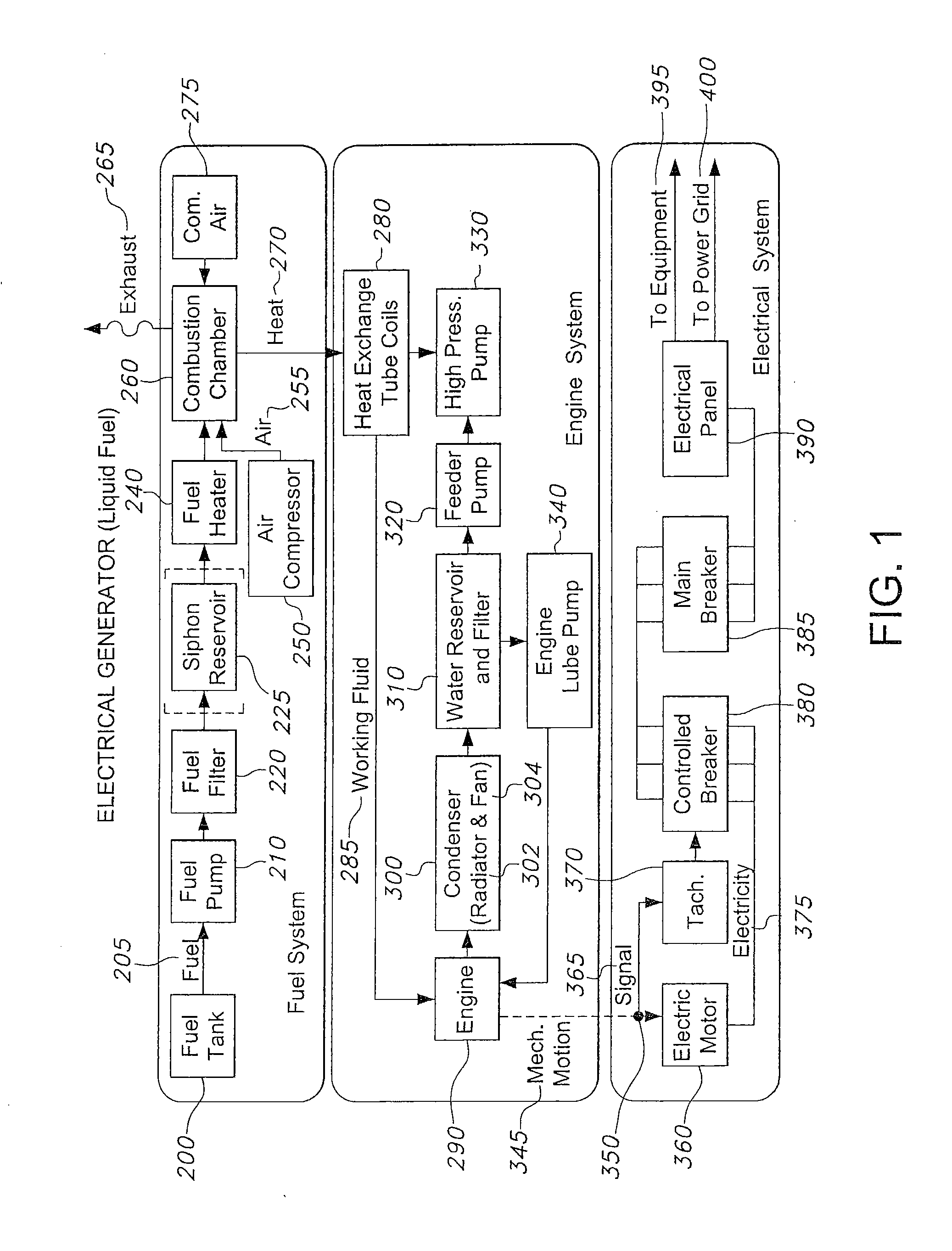
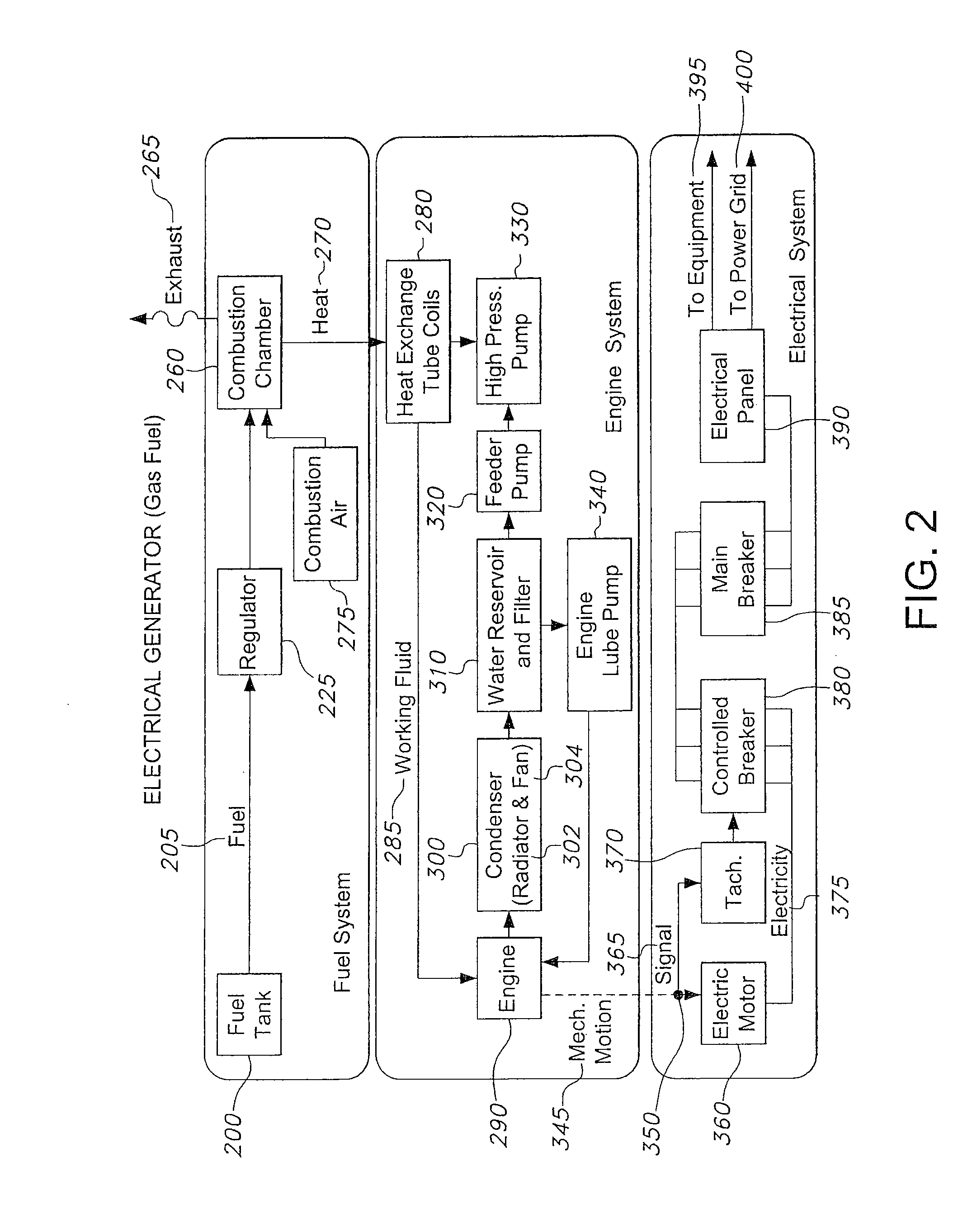
[0010]It is a distinct advantage of the present invention to provide a genset device that produces at least 6.0 kilowatts of electricity per hour of operation (preferably, at least 6.5, and more preferably at least 8.5) and that has a foot print of, at most, 13.5 square feet of area. It is another advantage of the inventive device and method to utilize the heat of a waste oil, syngases, natural gases, propane, methane, diesel, gasoline, and the like, directly connected to and present as the heat source for a heat regenerative engine to generate the minimum power levels noted above. Another advantage of this invention is the ability of the overall system to utilize a working fluid as a steam resource as well as an engine lubricant, all within a regenerative system that does not require any further introduction of working fluid therein. Additionally, another advantage of this invention is the capability to safely utilize air that is passed through the condensing system so as to provide a heat source within a certain space, open or confined thereby creating a CHP (combined heat and power) device. Yet another advantage of this invention is the capability of providing a suitable heat source through an exchanger that effectively exposes heating coils to different temperature levels, thereby according the working fluid present therein a gradual change from liquid to gaseous state and to a sufficiently high temperature to ensure efficient and high energy within an attached engine device. As well, another advantage is the ability to limit the generation of ash and other carbon byproducts by a combusting flame to areas that are in limited contact with working fluid coils, thus allowing for longer term burn and thus energy output without having to remove insulating byproducts from the coil surfaces. Additionally, a distinct advantage of this invention is the provision of relatively small tubing diameters that permit a greater amount of turns for the heating coils within the heat exchanger device, thus further permitting a larger amount of surface area for more efficient working fluid heating. Still another advantage of this invention is the ability of the heat exchanger to provide gradually increasing temperature levels to the small diameter heating coils in order to provide efficient vaporization followed by superheating to properly provide the desired working fluid in total gaseous state as it transports to an engine for energy conversion to motion.
[0011]Accordingly, this invention encompasses an all-in-one electrical generator that requires a total foot print of at most 4.6 square feet of area, wherein said generator includes a frame to which three separate major components are attached and configured in a stacked relation, or in a side by side relationship as the location may warrant, thereto, said components comprising: a) a heat generator component including i) a combustion chamber for the combustion and incineration of a volatile fuel that creates temperature sufficient to evaporate a working fluid into steam upon exposure thereto, ii) an ignition device to spark within said combustion chamber, iii) an air compressor (provided internally within or externally proximal to the system) to atomize a liquid fuel within said combustion chamber; iv) a heat exchanger including at least one small diameter coiled tube within which a working fluid is present and which, upon exposure to the heat generated by said heat generator component, evaporates to become steam therein; b) a steam engine component including i) a plurality of radially configured pistons present in substantially the same plane through which said steam from said heat exchanger passes to create piston movement thereby, ii) rotating a drive shaft, iii) a condenser comprising a cooling area through which said steam passes subsequent to passing through said pistons, v) a radiator, including a radiator fan to condense said steam into a working fluid condensate, or water to water plate heat exchanger along with a means to cool the cooling water (e.g. air handler), vi) a sump for collection of said condensate, vii) one pump to deliver at least a portion of said condensate to said heat exchanger for recycling therein and introduction back into said pistons, and viii) another pump to deliver at least a portion of said condensate to said pistons for lubrication thereof; and c) an electric generator component for which the movement of said drive shaft creates electrical charge; wherein said heat generator is connected directly to said heat exchanger to provide said sufficiently high temperature to said at least one coiled tube. Attached to such an electric generator may be any number of typical electrical system components to allow for transfer to either a specific piece of equipment or a power grid. The method of generating electrical charge through such a heat regenerative system is also encompassed within such an invention. The invention also encompasses, however, a novel heat exchanger device on its own that comprising a housing having a top panel, a bottom panel, two side panels, a front panel, and an end panel, wherein said housing includes therein a heating manifold formed by a refractory tube, wherein said refractory tube is configured in perpendicular relation to and extending from said front panel such that said tube includes an opening within said housing; wherein said housing includes a dividing tube that is configured in perpendicular relation to and extending from said end panel such that said tube includes an opening within said housing and within which is disposed said refractory tube; wherein said housing includes an energy retention disc disposed along the internal wall of said end panel, and thus substantially perpendicular to said dividing tube; wherein said housing includes at least one coiled tube encircling said dividing tube; and wherein said housing further includes at least two exhaust ports disposed within said end panel and with one of said ports disposed between said dividing tube and said top panel and the other disposed between said dividing tube and said bottom panel; wherein said coil tubing is disposed to carry a working fluid into said manifold from an entry point at said back end thereof to an egress point adjacent to the location of said opening between said internal cylinder edge and said front edge of sa

