Heating apparatus and method for fuel cell

a fuel cell and heating apparatus technology, applied in the field of heating apparatus and fuel cell, can solve the problems of difficult to determine the internal temperature distribution, time delay during cold-starting, and problems within the stack, and achieve the effect of reducing the cold-starting tim

Active Publication Date: 2014-07-03
HYUNDAI MOTOR CO LTD
View PDF2 Cites 3 Cited by
  • Summary
  • Abstract
  • Description
  • Claims
  • Application Information

AI Technical Summary

Benefits of technology

[0012]The present invention has been made in an effort to solve the above problems associated with the related art and an object of the present invention is to provide a heating method and apparatus for a fuel cell that reduce a cold-starting time through appropriate heating based in internal temperature distribution.

Problems solved by technology

Typically, in a fuel cell vehicle there is a time delay during cold-starting due to a difference in internal temperature of a stack.
Accordingly, some in the industry have proposed heating the frozen fuel cell stack to reduce the ice in the system, but in this process it is difficult to determine the internal temperature distribution.
This is because when a stack is heated with a uniform stack temperature distribution, the high-temperature area of the stack is overheated before the low-temperature area is unfrozen, which may cause issues within the stack.
Meanwhile, although the distribution of internal temperature of a stack of a fuel cell is an important parameter to determine, only very limited information has been known due to difficulty of mounting a fine internal structure sensor.
Therefore, since it is difficult to determine the internal temperature during cold-starting operation, the internal temperature is often estimated from the temperature of the air outlet, but these measurements are purely estimation and are not based on an actual distribution, since currently there is no technology for accurately determining the internal distribution.
Further, most of the technologies were implemented for the entire system of a stack due to the absence of internal information and there is no cold-starting technology for internal differences of a stack.
Therefore, it was required to find and heat a low-temperature area by accurately finding out the temperature differences, because supplying more thermal energy to improving cold-starting is a technology that is likely to cause problems relating to local overheating internally.
However, the above described structure does not improve the operability and stability of a fuel cell as efficiently as those skilled in the art may like.

Method used


Image

  • Heating apparatus and method for fuel cell
  • Heating apparatus and method for fuel cell
  • Heating apparatus and method for fuel cell

Examples


Embodiment Construction

[0022]It is understood that the term “vehicle” or “vehicular” or other similar term as used herein is inclusive of motor vehicles in general such as passenger automobiles including sports utility vehicles (SUV), buses, trucks, various commercial vehicles, watercraft including a variety of boats and ships, aircraft, and the like, and includes hybrid vehicles, electric vehicles, plug-in hybrid electric vehicles, hydrogen-powered vehicles and other alternative fuel vehicles (e.g. fuels derived from resources other than petroleum). As referred to herein, a hybrid vehicle is a vehicle that has two or more sources of power, for example both gasoline-powered and electric-powered vehicles.

[0023]Heating apparatuses for a fuel cell according to exemplary embodiments of the present invention are described hereafter with reference to the accompanying drawings.

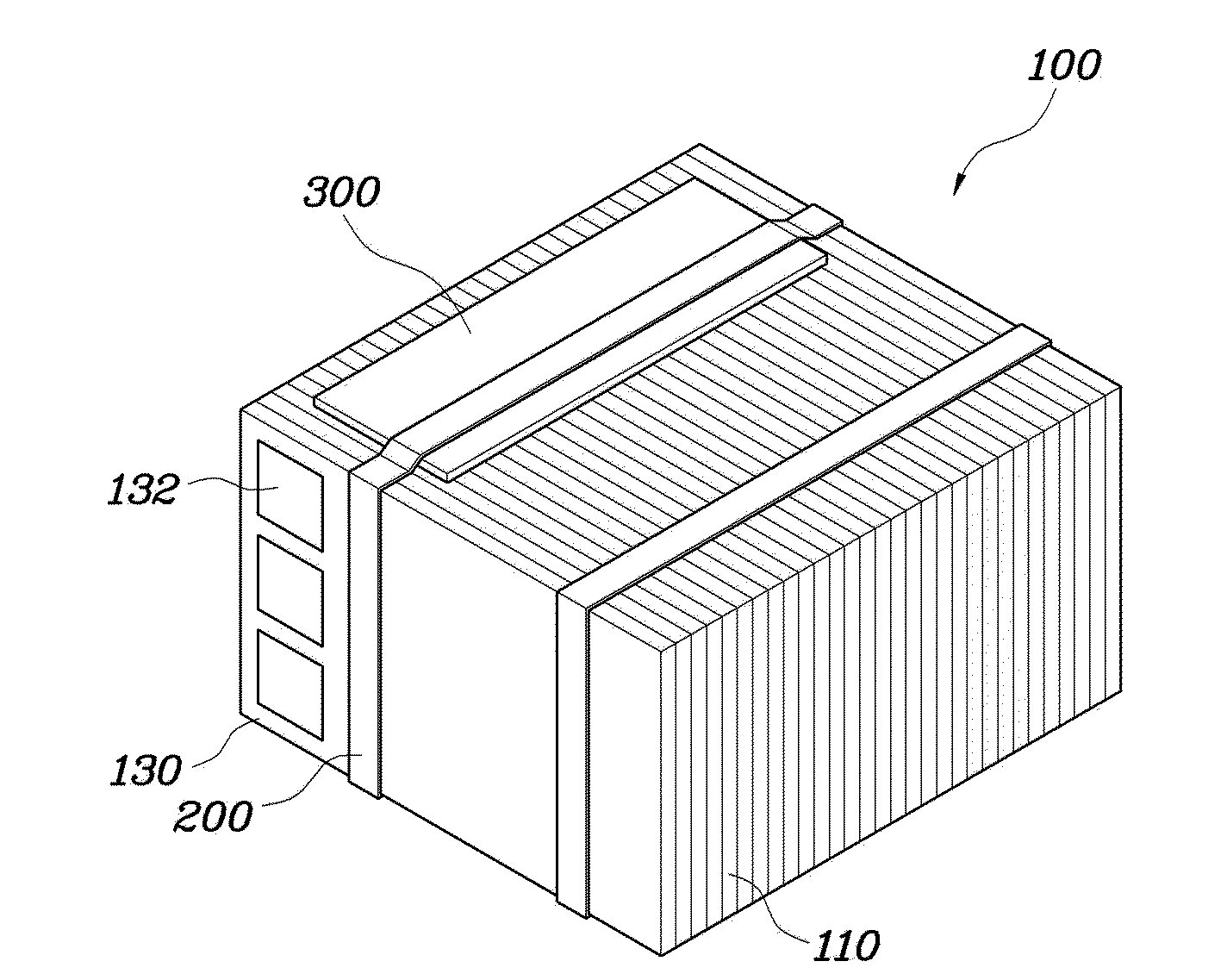
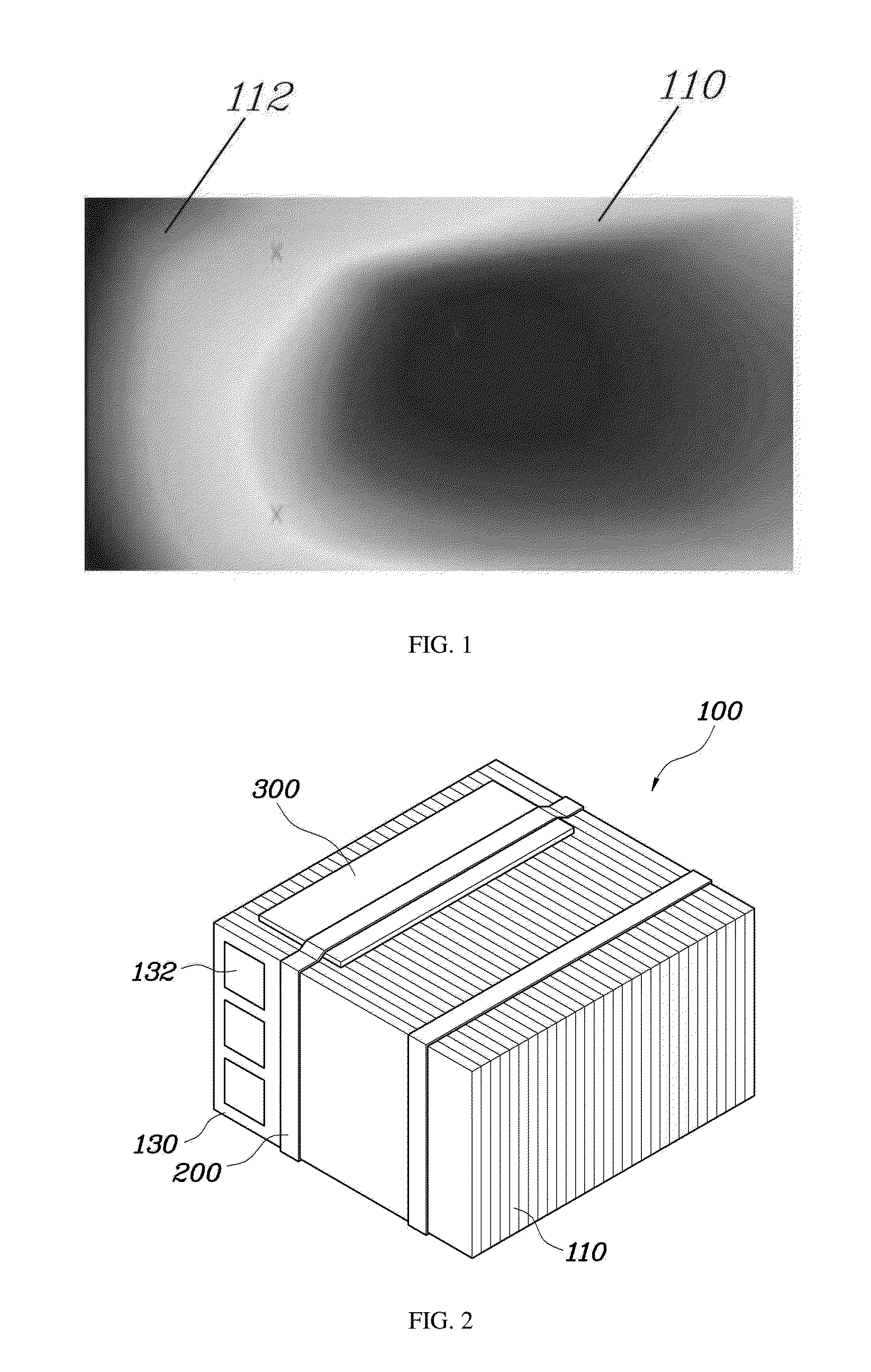
[0024]FIG. 1 is a illustration showing temperature distribution of a separator of a fuel cell, FIG. 2 is a perspective view of a heating ...


PUM

PropertyMeasurementUnit
temperature Tminaaaaaaaaaa
unit cell temperatureaaaaaaaaaa

Abstract

A heating apparatus for a fuel cell that includes heating units that extend in the stacking direction of a plurality of separators, in contact with upper ends and lower ends of air intake sides of the stacked separators.

Description

CROSS-REFERENCE TO RELATED APPLICATION[0001]This application claims under 35 U.S.C. §119(a) the benefit of Korean Patent Application No. 10-2012-0156289 filed Dec. 28, 2012, the entire contents of which are incorporated herein by reference.BACKGROUND[0002](a) Technical Field[0003]The present invention relate to a heating apparatus and method for a fuel cell which reduces a cold-starting time of a fuel cell vehicle, by appropriately heating the fuel cell based on an internal temperature distribution.[0004](b) Background Art[0005]Typically, in a fuel cell vehicle there is a time delay during cold-starting due to a difference in internal temperature of a stack. More specifically, a non-reacting low-temperature area and a reacting area locally and simultaneously increase in temperature due to ice blockage and the differences in internal temperature of a separator a when the vehicle is starting under cold weather conditions.[0006]Further, the maximum temperature Tmax occurs at the center...

Claims


Application Information

Patent Timeline
Patent Type & Authority Applications(United States)
IPC IPC(8): H01M8/04
CPCH01M8/04037H01M8/04007H01M2250/20H01M8/04067H01M8/04268Y02E60/50Y02T90/40H01M8/04H01M8/10
Inventor LEE, SUNG HOSHIM, SUN BO
Owner HYUNDAI MOTOR CO LTD
Why Eureka
Try Eureka