
Thermal energy storage and recovery arrangement

a technology of thermal energy and storage arrangement, applied in the direction of indirect heat exchangers, heat storage plants, lighting and heating apparatus, etc., can solve the problems of affecting the use of machinery, provoking some challenges, etc., and achieve the effect of less material problems

Inactive Publication Date: 2014-07-10
SIEMENS AG
View PDF0 Cites 32 Cited by
  • Summary
  • Abstract
  • Description
  • Claims
  • Application Information

AI Technical Summary

Benefits of technology

The patent is about a unit that can compress and expand a working medium. When it compresses the medium, it makes it more pressurized. When it expands the medium, it lowers the pressure. This unit can produce work that can be used to drive a compressor or a generator. The patent also suggests a method to improve the efficiency of the unit by controlling the temperature of the first thermal energy storage. This way, the unit can operate more effectively and at lower temperatures, reducing material problems and improving the overall performance of the system.

Problems solved by technology

However, using cold storages induces some challenges on the used machinery.

Method used


Image

  • Thermal energy storage and recovery arrangement
  • Thermal energy storage and recovery arrangement
  • Thermal energy storage and recovery arrangement

Examples


Embodiment Construction

[0061]The illustration in the drawings is in schematic form. It is noted that in different figures, similar or identical elements are provided with the same reference signs.

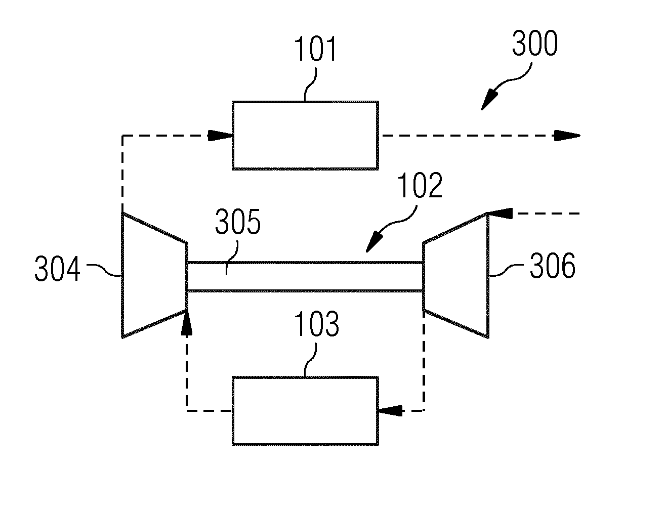
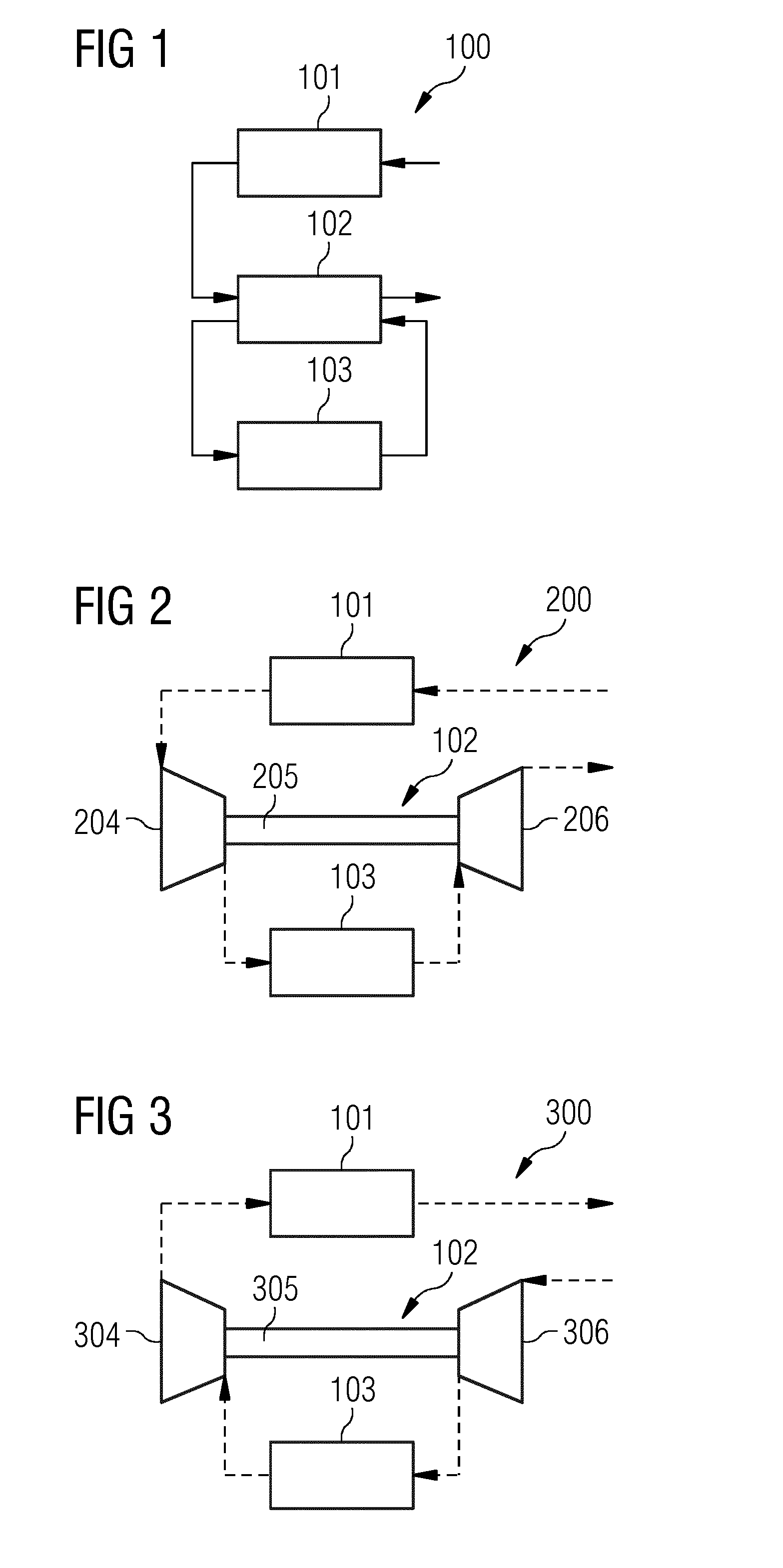
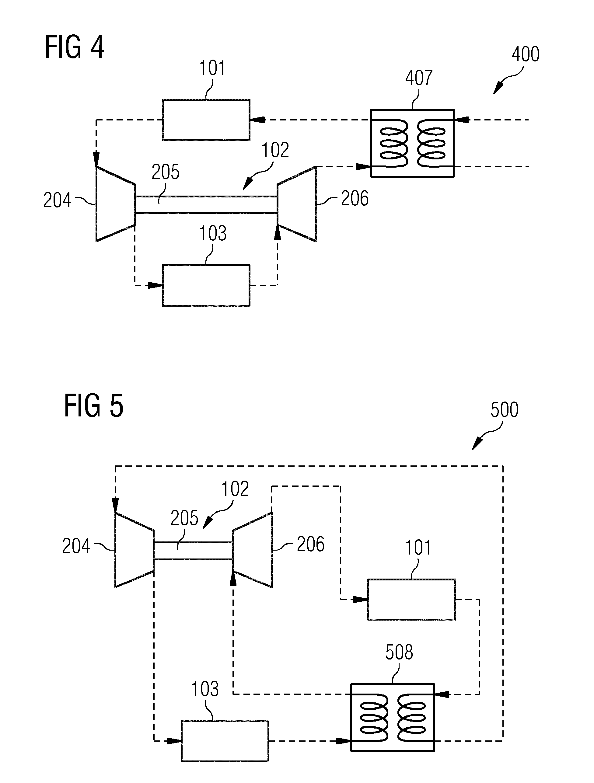
[0062]In FIG. 1, a thermal energy storage and recovery arrangement 100 according to an embodiment is shown. The thermal energy storage and recovery arrangement comprises a first thermal energy storage 101 and a second thermal energy storage 103. The first thermal energy storage is adapted to work at a temperature being equal to or higher than the ambient temperature. This means that the first thermal energy storage receives a working medium having a temperature equal to or higher than the ambient temperature and releases the working medium at a temperature equal to or higher than the ambient temperature. In one embodiment, the first thermal energy storage is adapted to receive as an input a working medium having ambient temperature and having ambient pressure. The second thermal energy storage is also adapted to ...


PUM


Abstract

A thermal energy storage and recovery arrangement is provided. The arrangement has a first thermal energy storage, a compression and expansion unit coupled thereto, and a second thermal energy storage coupled to the compression and expansion unit. The first and second thermal energy storage are adapted to work at a temperature equal to or higher than ambient temperature. In a charging mode, the first thermal energy storage is adapted for receiving and releasing thermal energy to a received working medium. The compression and expansion unit is adapted for receiving and compressing the working medium from the first thermal energy storage. The second thermal energy storage is adapted for receiving the compressed working medium and thermal energy therefrom and storing at least part of this energy. The compression and expansion unit is adapted for receiving the compressed working medium from the second thermal energy storage and expanding the compressed working medium.

Description

CROSS REFERENCE TO RELATED APPLICATIONS[0001]This application is the US National Stage of International Application No. PCT / EP2012 / 067120 filed Sep. 3, 2012, and claims the benefit thereof. The International Application claims the benefit of European Application No. EP11181344 filed Sep. 15, 2011. All of the applications are incorporated by reference herein in their entirety.FIELD OF INVENTION[0002]The present invention relates to the field of temporarily storing thermal energy. In particular, the present invention relates to a thermal energy storage and recovery arrangement comprising two thermal energy storages and a compression and expansion unit. Further, the present invention relates to a thermal energy storage and recovery system comprising such a thermal energy storage and recovery arrangement. Moreover, the present invention relates to a method for storing and recovering thermal energy.ART BACKGROUND[0003]The production of electric power from various types of alternative ene...

Claims


Application Information

Patent Timeline
IPC IPC(8): F28D20/00
CPCF28D20/00F28D20/0034Y02E60/14
Inventor LAURBERG, HANS
Owner SIEMENS AG
Learn More